
Wiring diagram with munit - REVIEW
- gordone
-
 Topic Author
- Offline
- Sustaining Member
-

Registered
- Posts: 1533
- Thanks: 93
Re: Wiring diagram with munit - REVIEW
14 Feb 2025 05:06 - 14 Feb 2025 05:06
Thank you !
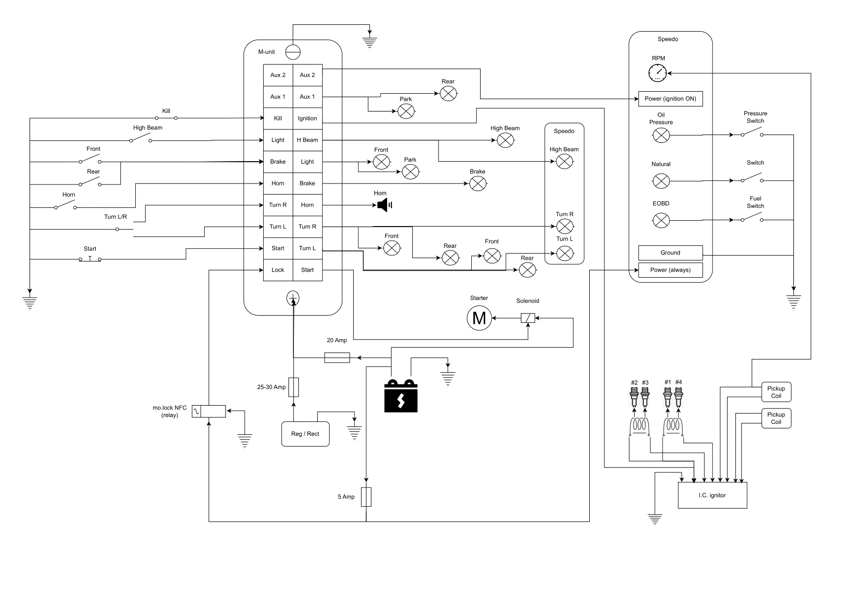
Updates:
1. I have renamed the input switch to High Beam
2. Increase the fuse from the regulator
3. Wired the park light to aux, same place where the rear light is connected, so I can use park light and rear light as you say if I switch to "Hi Beam" before you turn of the ignition.
What do you think, ready for building it ?")
Updates:
1. I have renamed the input switch to High Beam
2. Increase the fuse from the regulator
3. Wired the park light to aux, same place where the rear light is connected, so I can use park light and rear light as you say if I switch to "Hi Beam" before you turn of the ignition.
What do you think, ready for building it ?
1981 KZ650-D4, with 1981 z750L engine (Wiensco 810 big bore).
Project:
www.kzrider.com/forum/11-projects/607213...sr-1981-z750l-engine
Project:
www.kzrider.com/forum/11-projects/607213...sr-1981-z750l-engine
Last edit: 14 Feb 2025 05:06 by gordone.
Please Log in or Create an account to join the conversation.
- Wookie58
-

- Away
- Moderator
-

Registered
- Posts: 6110
- Thanks: 3847
Re: Wiring diagram with munit - REVIEW
14 Feb 2025 05:24
I would say "good to go"
1982 KZ1000 Ltd
www.kzrider.com/forum/11-projects/617631...-82-begins?start=192
kzrider.com/filebase-alias?view=download...d-fault-diagnosis&ca
www.kzrider.com/forum/11-projects/617631...-82-begins?start=192
kzrider.com/filebase-alias?view=download...d-fault-diagnosis&ca
The following user(s) said Thank You: gordone
Please Log in or Create an account to join the conversation.
- gordone
-
Topic Author
- Offline
- Sustaining Member
-
Registered
- Posts: 1533
- Thanks: 93
Re: Wiring diagram with munit - REVIEW
14 Feb 2025 11:17
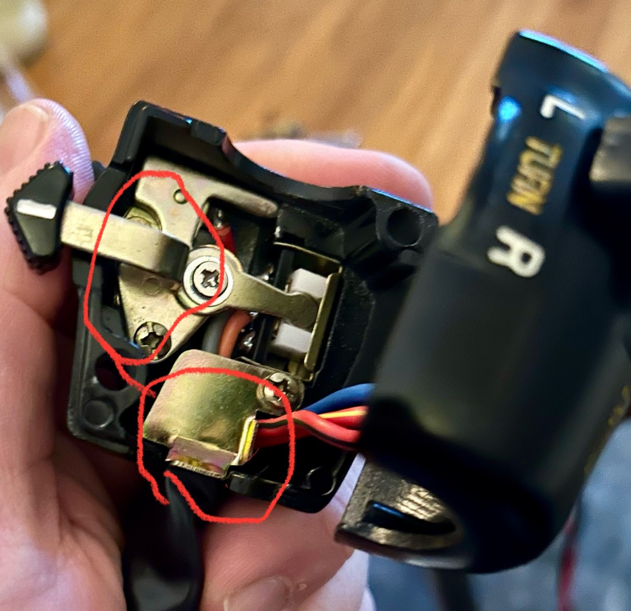
I have used a multimeter to find each «pair» on each switch on left and right handel bar switches.
the only one I don’t understand is Horn….
I cannot find the ground cable for horn?
But I get connection against the house and rhe two plates i dicated with red circle… so it has ground to the house case…
the only one I don’t understand is Horn….
I cannot find the ground cable for horn?
But I get connection against the house and rhe two plates i dicated with red circle… so it has ground to the house case…
1981 KZ650-D4, with 1981 z750L engine (Wiensco 810 big bore).
Project:
www.kzrider.com/forum/11-projects/607213...sr-1981-z750l-engine
Project:
www.kzrider.com/forum/11-projects/607213...sr-1981-z750l-engine
Please Log in or Create an account to join the conversation.
- F64
-

- Offline
- User
-

Registered
- 81-KZ440D2
- Posts: 1149
- Thanks: 417
Re: Wiring diagram with munit - REVIEW
14 Feb 2025 16:04 - 14 Feb 2025 19:41Does it have 1 wire at the horn?
If it does the the horn is grounded at the frame where it mounts.
The button controls a +12v line only.
You'll probably have to flip the button on the handlebar from +12v to ground.
I flipped everything in my handlebar switches to ground.
Of course this is just a guess--i have been absent for most of this thread.
ok, i looked at a schematic.
It looks like the horn button is grounded to the switch housing.
The switch housing will have to be installed on the handelbar and the handlebar grounded for the horn button to work and send a ground signal to your munit.
You could also run a separate ground wire to the switch housing just in case your handlebar is isolated from ground.
You should be able to get continuity between the switch housing bare metal(the bottom half where the button is located) and the horn wire coming out of the housing when you press the horn button.
81-KZ440-D2.
Louis Dudzik's GM HEI ignitor conversion installed 2015 s3.amazonaws.com/gpzweb/Ignition/GPZgmHEImod.html
Motogadget m-unit blue installed 2017.
LIC, NY
Louis Dudzik's GM HEI ignitor conversion installed 2015 s3.amazonaws.com/gpzweb/Ignition/GPZgmHEImod.html
Motogadget m-unit blue installed 2017.
LIC, NY
Last edit: 14 Feb 2025 19:41 by F64.
The following user(s) said Thank You: Wookie58
Please Log in or Create an account to join the conversation.
- gordone
-
Topic Author
- Offline
- Sustaining Member
-
Registered
- Posts: 1533
- Thanks: 93
Re: Wiring diagram with munit - REVIEW
14 Feb 2025 22:28Weired why they have done it like that… and only horn… I will try to to solid a new ground cable from a good place to a exsisting ground cable in the house. The house will not get ground it self, the steering has paint on the handelbar.Look at your horn.
Does it have 1 wire at the horn?
If it does the the horn is grounded at the frame where it mounts.
The button controls a +12v line only.
You'll probably have to flip the button on the handlebar from +12v to ground.
I flipped everything in my handlebar switches to ground.
Of course this is just a guess--i have been absent for most of this thread.
ok, i looked at a schematic.
It looks like the horn button is grounded to the switch housing.
The switch housing will have to be installed on the handelbar and the handlebar grounded for the horn button to work and send a ground signal to your munit.
You could also run a separate ground wire to the switch housing just in case your handlebar is isolated from ground.
You should be able to get continuity between the switch housing bare metal(the bottom half where the button is located) and the horn wire coming out of the housing when you press the horn button.
1981 KZ650-D4, with 1981 z750L engine (Wiensco 810 big bore).
Project:
www.kzrider.com/forum/11-projects/607213...sr-1981-z750l-engine
Project:
www.kzrider.com/forum/11-projects/607213...sr-1981-z750l-engine
Please Log in or Create an account to join the conversation.
- Wookie58
-
- Away
- Moderator
-
Registered
- Posts: 6110
- Thanks: 3847
Re: Wiring diagram with munit - REVIEW
15 Feb 2025 01:26 - 15 Feb 2025 01:49In the original OE set up the horn is the only "switched" ground. This is done to reduce wiring (and production cost) the car world does the same grounding horns to the steering column. If you follow the switch wiring configuration I gave you then blue the brown and the orange are already grounds so you can loop off of them rather than run an additional wire to the ground plate in the switchWeired why they have done it like that… and only horn… I will try to to solid a new ground cable from a good place to a exsisting ground cable in the house. The house will not get ground it self, the steering has paint on the handelbar.
ok, i looked at a schematic.
It looks like the horn button is grounded to the switch housing.
The switch housing will have to be installed on the handelbar and the handlebar grounded for the horn button to work and send a ground signal to your munit.
You could also run a separate ground wire to the switch housing just in case your handlebar is isolated from ground.
You should be able to get continuity between the switch housing bare metal(the bottom half where the button is located) and the horn wire coming out of the housing when you press the horn button.
1982 KZ1000 Ltd
www.kzrider.com/forum/11-projects/617631...-82-begins?start=192
kzrider.com/filebase-alias?view=download...d-fault-diagnosis&ca
www.kzrider.com/forum/11-projects/617631...-82-begins?start=192
kzrider.com/filebase-alias?view=download...d-fault-diagnosis&ca
Last edit: 15 Feb 2025 01:49 by Wookie58.
Please Log in or Create an account to join the conversation.
- gordone
-
Topic Author
- Offline
- Sustaining Member
-
Registered
- Posts: 1533
- Thanks: 93
Re: Wiring diagram with munit - REVIEW
15 Feb 2025 03:39 - 15 Feb 2025 08:06Ahh okay, added a exstra cable from the plate inside in the house (screw) to ground for left/right.In the original OE set up the horn is the only "switched" ground. This is done to reduce wiring (and production cost) the car world does the same grounding horns to the steering column. If you follow the switch wiring configuration I gave you then blue the brown and the orange are already grounds so you can loop off of them rather than run an additional wire to the ground plate in the switchWeired why they have done it like that… and only horn… I will try to to solid a new ground cable from a good place to a exsisting ground cable in the house. The house will not get ground it self, the steering has paint on the handelbar.
ok, i looked at a schematic.
It looks like the horn button is grounded to the switch housing.
The switch housing will have to be installed on the handelbar and the handlebar grounded for the horn button to work and send a ground signal to your munit.
You could also run a separate ground wire to the switch housing just in case your handlebar is isolated from ground.
You should be able to get continuity between the switch housing bare metal(the bottom half where the button is located) and the horn wire coming out of the housing when you press the horn button.
thank you
1981 KZ650-D4, with 1981 z750L engine (Wiensco 810 big bore).
Project:
www.kzrider.com/forum/11-projects/607213...sr-1981-z750l-engine
Project:
www.kzrider.com/forum/11-projects/607213...sr-1981-z750l-engine
Last edit: 15 Feb 2025 08:06 by gordone.
The following user(s) said Thank You: Wookie58
Please Log in or Create an account to join the conversation.
- gordone
-
Topic Author
- Offline
- Sustaining Member
-
Registered
- Posts: 1533
- Thanks: 93
Re: Wiring diagram with munit - REVIEW
19 Feb 2025 23:32
Cable size when it comes to IC unit and coils, can I use 0,5^2mm or do I need to use 1,5^2 ?
In general my plan:
0,5^2mm - cabling betweeen switches and M-unit input
1,5^2mm - to lights and horn
2,5^2mm - to starter motor
In general my plan:
0,5^2mm - cabling betweeen switches and M-unit input
1,5^2mm - to lights and horn
2,5^2mm - to starter motor
1981 KZ650-D4, with 1981 z750L engine (Wiensco 810 big bore).
Project:
www.kzrider.com/forum/11-projects/607213...sr-1981-z750l-engine
Project:
www.kzrider.com/forum/11-projects/607213...sr-1981-z750l-engine
Please Log in or Create an account to join the conversation.
- Wookie58
-
- Away
- Moderator
-
Registered
- Posts: 6110
- Thanks: 3847
Re: Wiring diagram with munit - REVIEW
20 Feb 2025 01:51
1982 KZ1000 Ltd
www.kzrider.com/forum/11-projects/617631...-82-begins?start=192
kzrider.com/filebase-alias?view=download...d-fault-diagnosis&ca
www.kzrider.com/forum/11-projects/617631...-82-begins?start=192
kzrider.com/filebase-alias?view=download...d-fault-diagnosis&ca
The following user(s) said Thank You: gordone, Scirocco
Please Log in or Create an account to join the conversation.
- gordone
-
Topic Author
- Offline
- Sustaining Member
-
Registered
- Posts: 1533
- Thanks: 93
Re: Wiring diagram with munit - REVIEW
26 Feb 2025 11:22
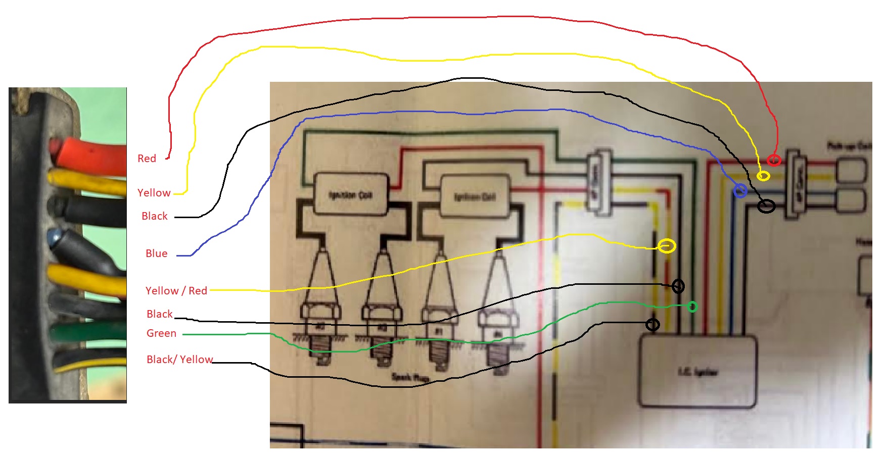
I just want to double check I have understood the wiring og IC and coil correct, please see attached photo:
1981 KZ650-D4, with 1981 z750L engine (Wiensco 810 big bore).
Project:
www.kzrider.com/forum/11-projects/607213...sr-1981-z750l-engine
Project:
www.kzrider.com/forum/11-projects/607213...sr-1981-z750l-engine
Please Log in or Create an account to join the conversation.
- Wookie58
-
- Away
- Moderator
-
Registered
- Posts: 6110
- Thanks: 3847
Re: Wiring diagram with munit - REVIEW
26 Feb 2025 11:48
Looks correct to me
1982 KZ1000 Ltd
www.kzrider.com/forum/11-projects/617631...-82-begins?start=192
kzrider.com/filebase-alias?view=download...d-fault-diagnosis&ca
www.kzrider.com/forum/11-projects/617631...-82-begins?start=192
kzrider.com/filebase-alias?view=download...d-fault-diagnosis&ca
The following user(s) said Thank You: gordone
Please Log in or Create an account to join the conversation.
- gordone
-
Topic Author
- Offline
- Sustaining Member
-
Registered
- Posts: 1533
- Thanks: 93
Re: Wiring diagram with munit - REVIEW
27 Feb 2025 03:46
Thank you !
How do you normally fasten these DTM connectors, so they are not loose?
How do you normally fasten these DTM connectors, so they are not loose?
1981 KZ650-D4, with 1981 z750L engine (Wiensco 810 big bore).
Project:
www.kzrider.com/forum/11-projects/607213...sr-1981-z750l-engine
Project:
www.kzrider.com/forum/11-projects/607213...sr-1981-z750l-engine
Please Log in or Create an account to join the conversation.
Moderators: Street Fighter LTD