
CSR1000 Project Build
- davido
-
 Topic Author
- Offline
- User
-

Registered
- Posts: 1580
- Thanks: 291
Re: CSR1000 Project Build
01 May 2016 07:44
Ok,Good news and bad news. I was working through your guide,Wrenchmonkey, and I tested from the grey wire to the battery,I got 5volts showing with the switch to the left and 5 volts with the switch to the right.
I disconnected the switch unit from the loom and did a continuity test.Everything was good with the switch.
I got 2 new flasher units (3 point ones) connected the common orange from the fusebox to the x terminals and the orange and the orange/green to the L terminals. Still nothing.
Then I disconnected the blue wires ( running lights) from the front indicators and hey presto. Everything started working!?!.Fantastic!
So,I thought,Whats going on here? I plugged the blue wires back in and nothing. Took them out again and...nothing!
I checked the schematic again and that small diode that I was wondering about,is on the blue wire.Well it should be but its missing on my loom and where it should be,(Joining the blue wire to the red,tail light wire) its just spliced together with no diode.
Im guessing that this might be something to do with the problem. I understand what a diode is meant to do though I have no idea why there should be one fitted here.I will have to find one and replace it then, before I can go on.Bugger!
www.kzrider.com/forum/11-projects/594313-csr1000-project-build
CB550 (1978)
CB500/4 (1972)*
KZ1000CSR (1981)
XT 600E (1999)
TDM900 (2003)
CB550 (1978)
CB500/4 (1972)*
KZ1000CSR (1981)
XT 600E (1999)
TDM900 (2003)
Please Log in or Create an account to join the conversation.
- wrenchmonkey
-
- Offline
- User
-
Registered
- Posts: 568
- Thanks: 75
Re: CSR1000 Project Build
01 May 2016 08:37 - 01 May 2016 08:43
Great news!  Damn!
Damn! 
I was just perusing the diagram again to follow your experiences.
What happens if you separate the wires where the diode should be?
For whatever reason, that diode allows current flow to go only one way - toward the tail lights. The diode there means Mama Kaw didn't want current flow to return across that diode from rear light to front lights. I dunno why that could ever be except maybe as a safety system - as in, parking lot clown backs into your bike and crushes the tail light for example, potentially shorting the tail light.
Per the diagram the electrical source for the running lights comes directly from the ignition switch on the black/white wire, which powers-up 3 fuses, the output on the 3rd fuse with the red/white wire turns on the running lights front and back (via that absent diode).
BUT
There is another red wire on the tail light side of that diode which splits off and goes back to the ignition switch too...
This is why I wondered what would happen if you simply separate that wire at the diode placement to create an open?
In effect, it "opens" the circuit from front to back running lights.
Based upon this diagram, your front "running lights" on the blue wires, should turn on, while your rear running lights on the red wire may not...depending on what that other red wire going to the ignition switch is actually doing?
What I find interesting is the source for the turn signals is independent of the running lights. Signal lights get power from ignition switch on a separately fused circuit... which goes to the flasher relays and then to the switch and then finally the signal lights.
Hmm?
This kinda puts the ignition switch as a possible common denominator.
So for grins and giggles:
What would happen if you left the ignition switch OFF.
Temporarily disconnect the Orange/Green wire from the fuse that supports the turn signal circuit (output is orange only wire).
Make a temporary jumper wire from the Battery (+) terminal TO the INPUT side of the erstwhile Orange/Green fuse..
This would in effect test the turn signal circuit ONLY..
Do your turn signals work as normal?
AHHH!
Quick thought... All the turn signal bulbs (hell, every bulb for this matter) are the correct types right? I mean PO didn't accidentally put dual element bulbs in the rear turn signals or single element bulbs in the front..? I've seen that before... mixed up the contact points AT the bulbs.. criss crossing circuits in random ways...
Damn! I was just perusing the diagram again to follow your experiences.
What happens if you separate the wires where the diode should be?
For whatever reason, that diode allows current flow to go only one way - toward the tail lights. The diode there means Mama Kaw didn't want current flow to return across that diode from rear light to front lights. I dunno why that could ever be except maybe as a safety system - as in, parking lot clown backs into your bike and crushes the tail light for example, potentially shorting the tail light.
Per the diagram the electrical source for the running lights comes directly from the ignition switch on the black/white wire, which powers-up 3 fuses, the output on the 3rd fuse with the red/white wire turns on the running lights front and back (via that absent diode).
BUT
There is another red wire on the tail light side of that diode which splits off and goes back to the ignition switch too...
This is why I wondered what would happen if you simply separate that wire at the diode placement to create an open?
In effect, it "opens" the circuit from front to back running lights.
Based upon this diagram, your front "running lights" on the blue wires, should turn on, while your rear running lights on the red wire may not...depending on what that other red wire going to the ignition switch is actually doing?
What I find interesting is the source for the turn signals is independent of the running lights. Signal lights get power from ignition switch on a separately fused circuit... which goes to the flasher relays and then to the switch and then finally the signal lights.
Hmm?
This kinda puts the ignition switch as a possible common denominator.
So for grins and giggles:
What would happen if you left the ignition switch OFF.
Temporarily disconnect the Orange/Green wire from the fuse that supports the turn signal circuit (output is orange only wire).
Make a temporary jumper wire from the Battery (+) terminal TO the INPUT side of the erstwhile Orange/Green fuse..
This would in effect test the turn signal circuit ONLY..
Do your turn signals work as normal?
AHHH!
Quick thought... All the turn signal bulbs (hell, every bulb for this matter) are the correct types right? I mean PO didn't accidentally put dual element bulbs in the rear turn signals or single element bulbs in the front..? I've seen that before... mixed up the contact points AT the bulbs.. criss crossing circuits in random ways...
Last edit: 01 May 2016 08:43 by wrenchmonkey.
Please Log in or Create an account to join the conversation.
- davido
-
Topic Author
- Offline
- User
-
Registered
- Posts: 1580
- Thanks: 291
Re: CSR1000 Project Build
01 May 2016 10:20
Aha! Well I diconnected the diode wires and the headlight went out. I reconnected them and the headlight came on again. I disconnected them again and the headlight stayed on????.
So,I put everything together again (back to default)and disconnected the feed from the ignition switch(orange/green) ran a wire from the orange directly to the battery (+) and the indicators started working! Front,back,left and right.Hoorah!
So,this would indicate a problem with the ignition switch,no?
OR,
The other day,I unplugged the blue wire.everything worked,I plugged it in again everything didnt work,I unplugged it again and it still didnt work.Same as above with the diode wires and the headlight. This would point to a loose connection somewhere that I disturb during the plugging/unplugging.
What do you think?
Also,the bulbs in the indicators are good.The front are double elements in the original holders the rear are a set of aftermarket single elements from my parts box. I have another set of singles from an old Honda which I tried.All of them have tested positive
www.kzrider.com/forum/11-projects/594313-csr1000-project-build
CB550 (1978)
CB500/4 (1972)*
KZ1000CSR (1981)
XT 600E (1999)
TDM900 (2003)
CB550 (1978)
CB500/4 (1972)*
KZ1000CSR (1981)
XT 600E (1999)
TDM900 (2003)
Please Log in or Create an account to join the conversation.
- wrenchmonkey
-
- Offline
- User
-
Registered
- Posts: 568
- Thanks: 75
Re: CSR1000 Project Build
01 May 2016 13:48
Cool! ")
Kinda' makes you feel a wee bit like Sherlock Holmes on the case; eh?
Typically, I would do the same thing as you did with the signal lighting circuit - make a temporary wire from battery to it and isolate that what you can individually - ie: you know, now, that the flasher/signal circuit is functioning fine on it's own.
You may find that the ignition switch is "wonky". Sorta' working sometimes and then sometimes not so much. Usually you can isolate this by jiggling the key and causing the contacts inside the switch to wiggle a bit and see if things change up or not.
The fact that you get a "works!"..."Doesn't work!" situation sure makes me think you have quasi contacting somewhere. Maybe oxidation on the fuse links or connections OR ignition switch.
Please Log in or Create an account to join the conversation.
- davido
-
Topic Author
- Offline
- User
-
Registered
- Posts: 1580
- Thanks: 291
Re: CSR1000 Project Build
06 May 2016 12:46
Isolating the circuit was your idea Wrenchmonkey,I take no credit for any of it. Following your advice. I pulled the ignition switch apart (very simple as the bottom just pops off though there are springs and spring loaded ball bearings inside,so very happy I didnt lose anything . I gave it all a good clean and put it back together. I also found the orange wire was oxodized at the solder point and though it was still connected,it was only by 3 or 4 strands that had gone green. So,I cleaned that up,spliced in a fresh bit of wire with some shrink wrap around it.
The situation now is that everything works!!!! with the running lights disconnected!!! With them connected,everything works except the front indicators!?!.
As I said earlier,Ive never had running lights,I dont know what theyre for or how they work.Can you turn them on and off? do they go off automatically? I dont want them but I would like to know how theyre meant to work.
www.kzrider.com/forum/11-projects/594313-csr1000-project-build
CB550 (1978)
CB500/4 (1972)*
KZ1000CSR (1981)
XT 600E (1999)
TDM900 (2003)
CB550 (1978)
CB500/4 (1972)*
KZ1000CSR (1981)
XT 600E (1999)
TDM900 (2003)
Please Log in or Create an account to join the conversation.
- wrenchmonkey
-
- Offline
- User
-
Registered
- Posts: 568
- Thanks: 75
Re: CSR1000 Project Build
06 May 2016 20:31
Hey davido! Congratulations for sleuthing it out and for having the nerve to dismantle the ignition switch. I've tried that before with less than ideal results - spring and ball bearings went ... erm, decided they wanted to hide under my workbench forever. LOL
So "Running lights" were simply a decision forced upon the riders on this side of the big pond by a governing body. Just like the headlamp which comes on with ignition key and stays on. There is no off switch for either (save for the ignition's Off) and their purpose was to make motorcyclists more visible to other motorists whom today at least, seem preoccupied with their cellphones than the road in front of them. This law however, was created decades ago; long before cellular phones in automobiles.
I remember buying a brand new 1978 GS400 and the headlamp Off/On/High Beam switch was still on the bike but the manufacturer (or maybe it was the dealer?) had installed this little metal bar which stopped the switch from clicking back to the Off position. It was such an agricultural "fix" and looked like an obvious afterthought. Sigh. When our governments know better than us mere constituents
Back on the subject however, I'm puzzled by the signal lamps not working just because you disconnect the running lights? That's totally weird. I mean even while it's the same bulb, it's two circuits from the bike's perspective.
How are you disconnecting the running lights?
You are pulling the blue wire from each bulb holder's barrel connector; I assume?
It could be possible that the ground strap for the signal lamps is weak or not present. A circuit for the turn signal element, can use the running light circuit as it's ground. Kinda' like running the bulbs in series. Two circuits go into the bulb but without the external grounding of the bulb holder, the running light circuit acts like a ground to the signal lamp. I bet this is what's going on... At least I've seen this before on old 6 volt, vintage cars. The game is afoot Dr.Watson! :laugh:
Please Log in or Create an account to join the conversation.
- davido
-
Topic Author
- Offline
- User
-
Registered
- Posts: 1580
- Thanks: 291
Re: CSR1000 Project Build
22 May 2016 06:44
Update time. I think the electrics are sorted for now. I never got to the bottom of the running light puzzle but Im beyond caring.They are disconnected (blue wires) and wont be coming back.Ill be replacing all the indicators and Ill fit single elements on the front as well as the back.
Next was getting the European (ZXR) switches plumbed in to the American CSR loom..That was fun.I started by printing out the CSR schematic,the ZXR schematic and a 1980s European Z1000 schematic. Then I got out the scissors,tape and felt tip pens. Cutting out bits of schematics and pasting them together. After a lot of faffing around,I got it sorted. On paper.Next was to raid the parts bin for a load of scrap wire (mostly old CB550) and try it out for real .It was a big mess with odd bits of wire stretched from here to there,a combination of spade and bullet connections and a few wires just twisted together.but it all seems to work. Ive got on/off headlight.High/low,Indicators and a pass light instead of hazards.
So,in short,it works!!!! Which is pretty amazing, As I said before,Im not a sparky kind of guy,so to have done this,succesfully is great.
Saying that,Hats off to Wrenchmonkey.Many thanks man. Without your help I would be still scratching my balls staring at it.
Next step, New battery box,fuse box and assorted mounts that will go there abouts.
www.kzrider.com/forum/11-projects/594313-csr1000-project-build
CB550 (1978)
CB500/4 (1972)*
KZ1000CSR (1981)
XT 600E (1999)
TDM900 (2003)
CB550 (1978)
CB500/4 (1972)*
KZ1000CSR (1981)
XT 600E (1999)
TDM900 (2003)
Please Log in or Create an account to join the conversation.
- davido
-
Topic Author
- Offline
- User
-
Registered
- Posts: 1580
- Thanks: 291
Re: CSR1000 Project Build
22 May 2016 06:57
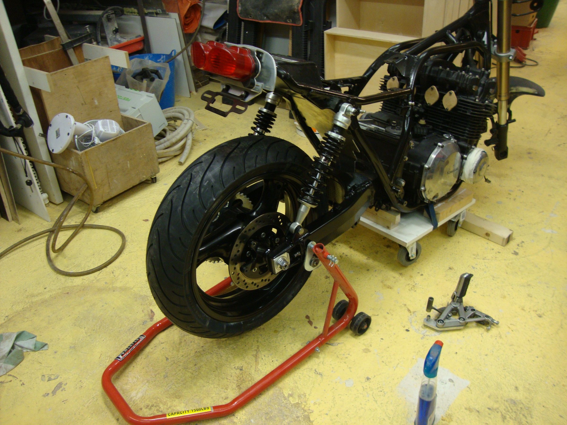
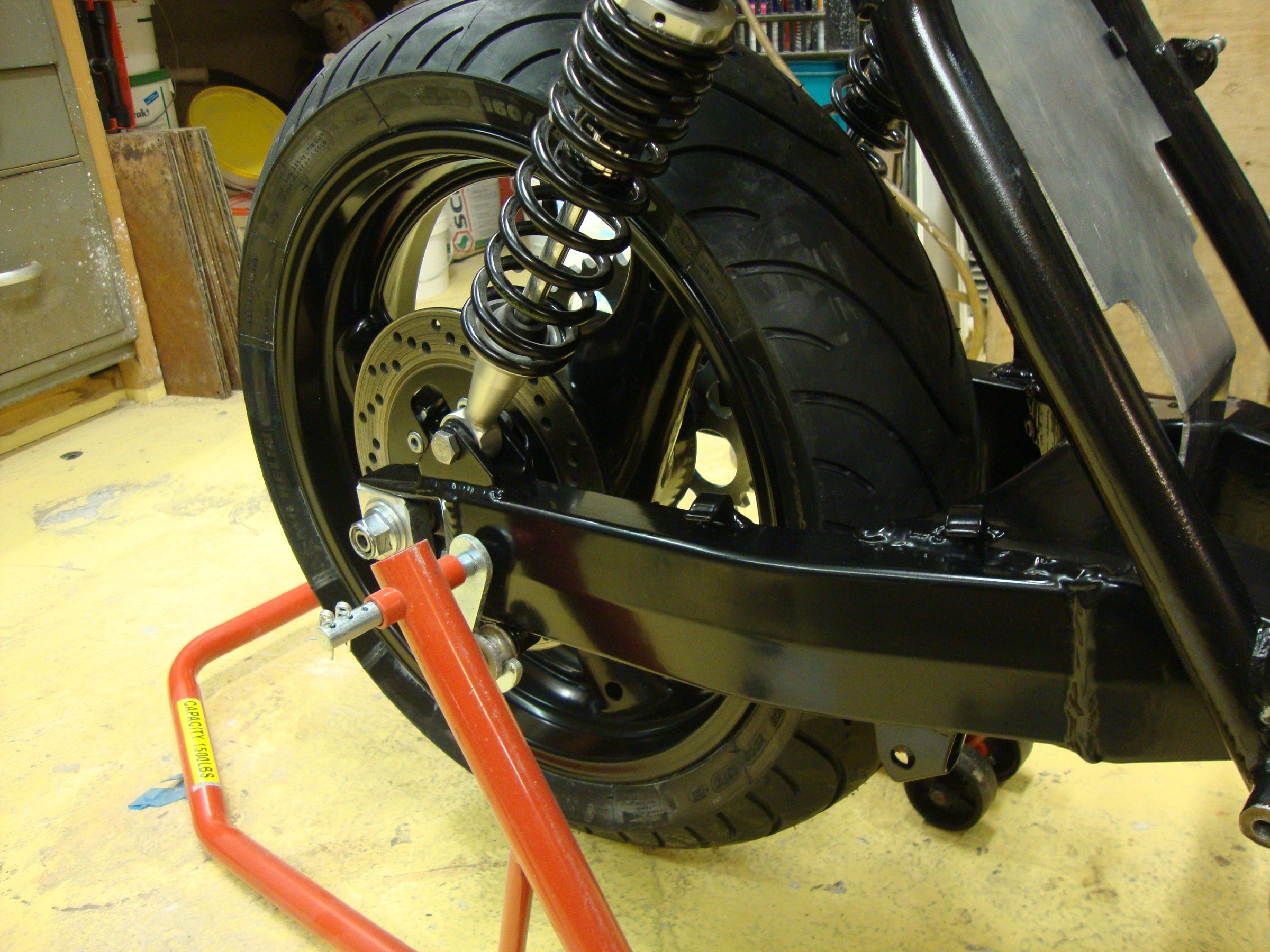
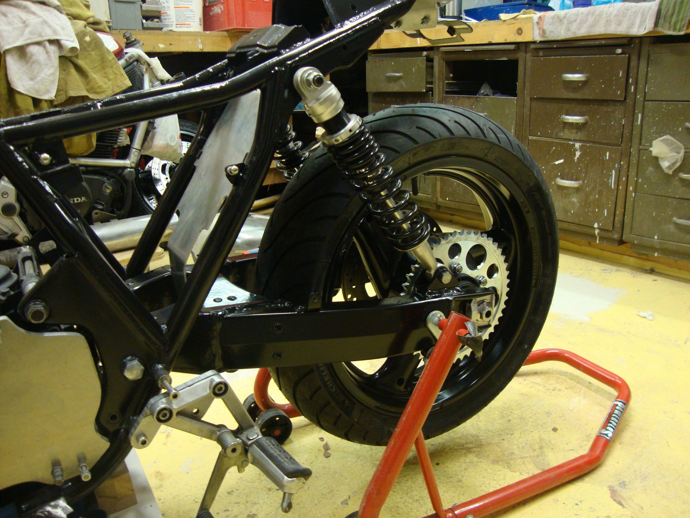
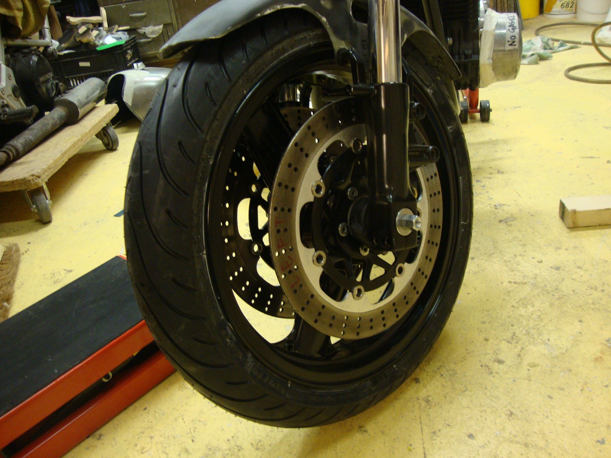
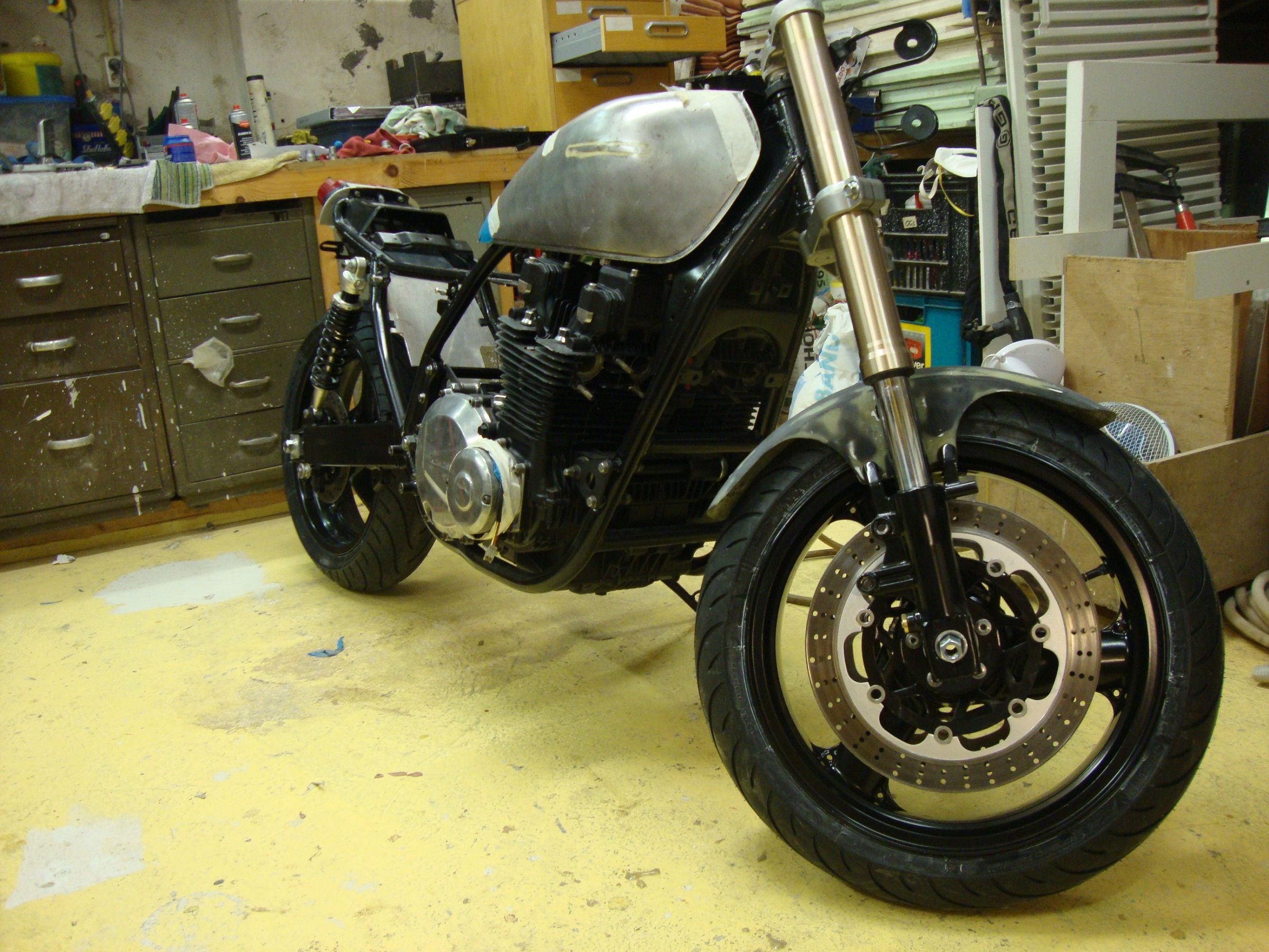
Big day today.My baby got new shoes! Yes,wheels and swinger back from the powdercoaters. I am not going to get into how disappointing the whole experience has been,Im wearing my positive trousers today so I just got on with it and finally got everything fitted.
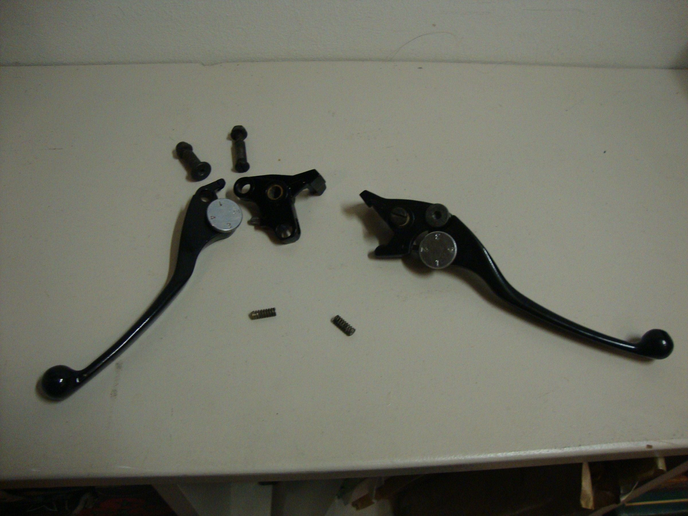
Onward and upward. I was also wanting to work on the steering today and got out my nice freshly painted levers only to find that I cant remember how the buggers go together.
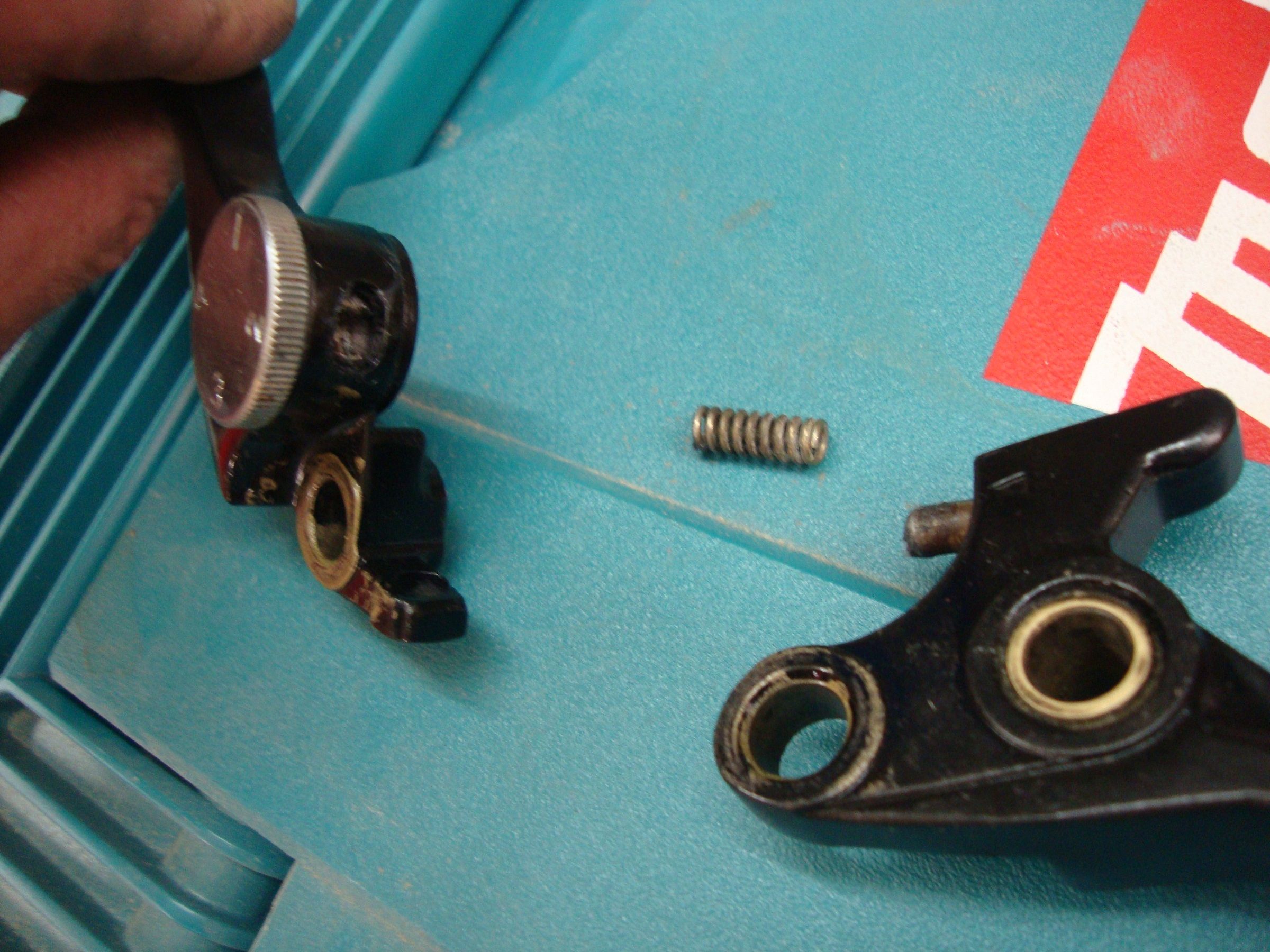
Am I missing a part here? When I put the 2 parts together there is no tension and they flop about.I found a couple of small springs. Are they part of the assembly,or from something else?? Grateful for any help with this.
Onward and upward. I was also wanting to work on the steering today and got out my nice freshly painted levers only to find that I cant remember how the buggers go together.
Am I missing a part here? When I put the 2 parts together there is no tension and they flop about.I found a couple of small springs. Are they part of the assembly,or from something else?? Grateful for any help with this.
www.kzrider.com/forum/11-projects/594313-csr1000-project-build
CB550 (1978)
CB500/4 (1972)*
KZ1000CSR (1981)
XT 600E (1999)
TDM900 (2003)
CB550 (1978)
CB500/4 (1972)*
KZ1000CSR (1981)
XT 600E (1999)
TDM900 (2003)
Please Log in or Create an account to join the conversation.
- wrenchmonkey
-
- Offline
- User
-
Registered
- Posts: 568
- Thanks: 75
Re: CSR1000 Project Build
22 May 2016 09:28
Wow! :ohmy:
That bike is looking totally righteous David. You're doing an awesome job of it man!
That swing arm with those forks is quite the transformation. I can hardly wait to see the full effect.
Really dig the tail light too!
Wish I could help with the levers but my CSR has both replaced before I took-on the project.
It's hard to see from that one picture which lever it is? - Right side brake (where's the master cylinder reservoir?) or left side clutch (and what's that dial for?).
Using my foggy noodle on limited coffee as yet; I'm going to guess it's your clutch lever/perch!
On my bikes the clutch lever is "floppy" until it's installed and connected to the clutch which is what gives it the return-spring feeling.
If that is your clutch, then, the spring and little pin is for the ignition lock-out switch; right? Must pull clutch lever to start engine... At least that's how it is on this side of the big pond. The actual switch is controlled by the small tab that is cast into the lever portion nearest the case-line of that blue makita box it's sitting on.
There should be some small wire terminals visible on the underside of the perch portion.
The furthest forward hole would be the pivot point then. I think? So hard to tell from here. Neeeed morrrre caaffffeine...
Please Log in or Create an account to join the conversation.
- davido
-
Topic Author
- Offline
- User
-
Registered
- Posts: 1580
- Thanks: 291
Re: CSR1000 Project Build
23 May 2016 12:57
Ok,my questiion was maybe a bit vague.Sorry about that To clarify.The levers are standard ZXR levers, (both hydraulic) ,with 4-way adjustment dials. No problems with the mounting to the master cylinders and handelbars. The system is quite common on modern bikes,in fact I have the same thing on my Bandit,I just wanted to ask here before pulling that apart.
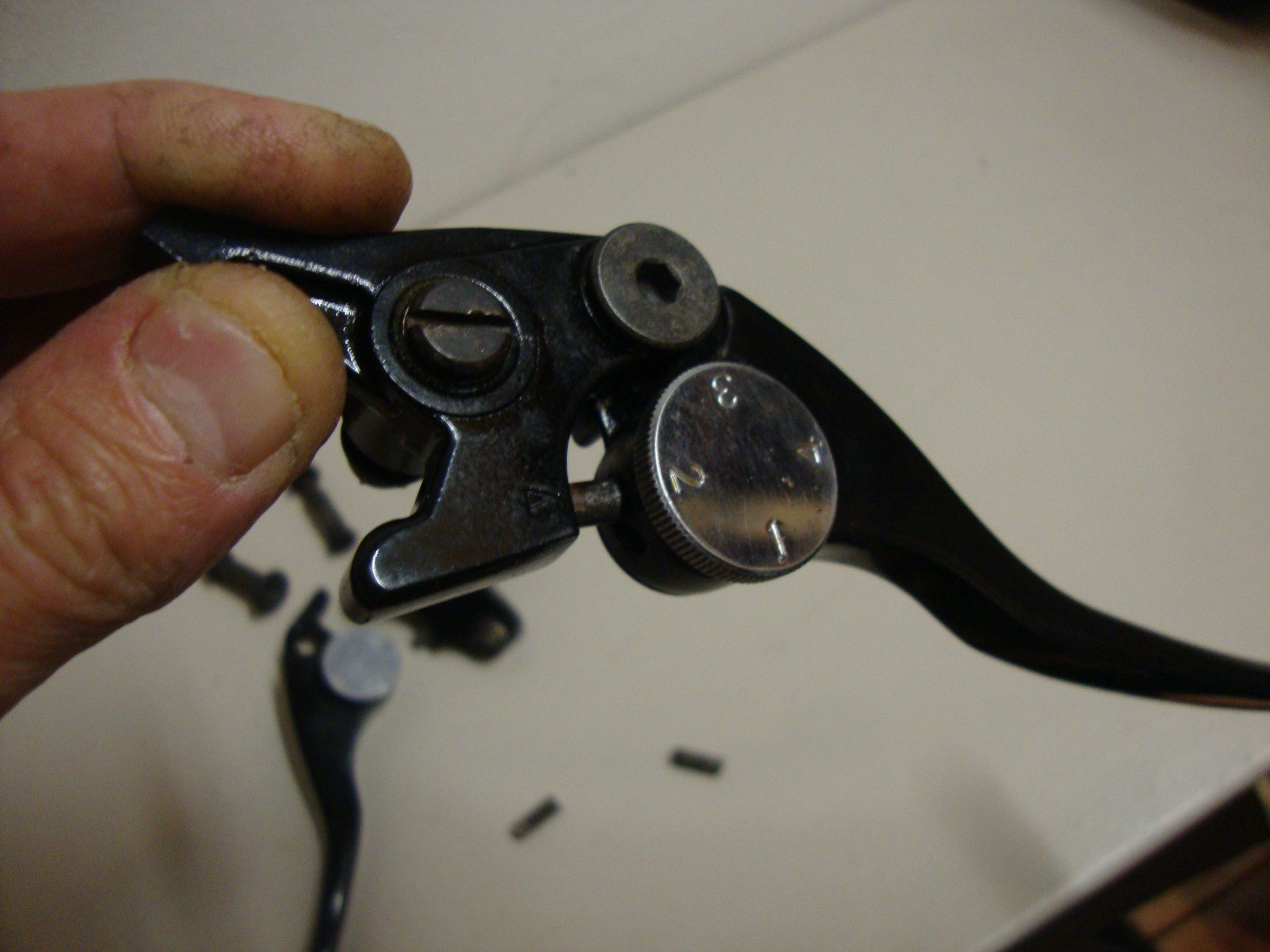
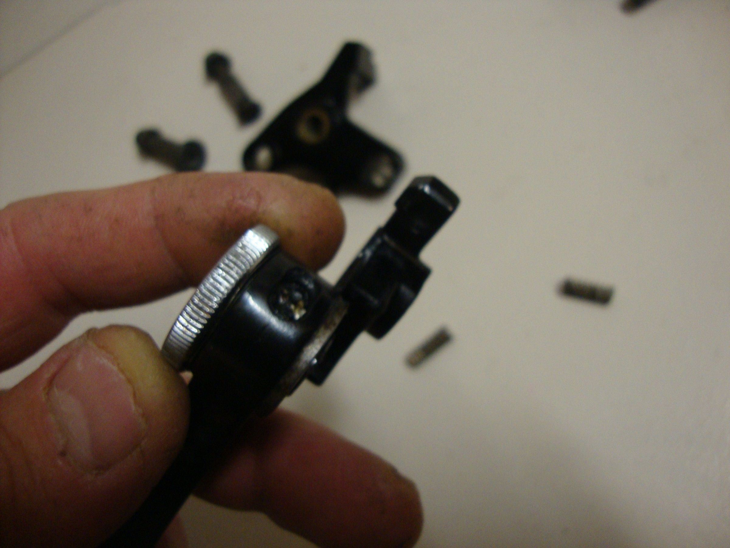
Here are some better pictures (Part No.13236 in the schematic). This is what Ive got;
[attachment:4]kawasaki-zx900b1-ninjazx9r-1994-eu-uk-fr-nl-ar-fg-gr-it-nr-sd-sp-st-front-master-cylinder_bigkae0484f2291_7e03.gif[/attachment)
Question being, how do they go together. Am I missing something?????
Here are some better pictures (Part No.13236 in the schematic). This is what Ive got;
[attachment:4]kawasaki-zx900b1-ninjazx9r-1994-eu-uk-fr-nl-ar-fg-gr-it-nr-sd-sp-st-front-master-cylinder_bigkae0484f2291_7e03.gif[/attachment)
Question being, how do they go together. Am I missing something?????
www.kzrider.com/forum/11-projects/594313-csr1000-project-build
CB550 (1978)
CB500/4 (1972)*
KZ1000CSR (1981)
XT 600E (1999)
TDM900 (2003)
CB550 (1978)
CB500/4 (1972)*
KZ1000CSR (1981)
XT 600E (1999)
TDM900 (2003)
Please Log in or Create an account to join the conversation.
- TexasKZ
-

- Offline
- Platinum Member
-

Registered
- Posts: 8268
- Thanks: 2723
Re: CSR1000 Project Build
23 May 2016 17:47
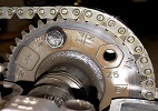
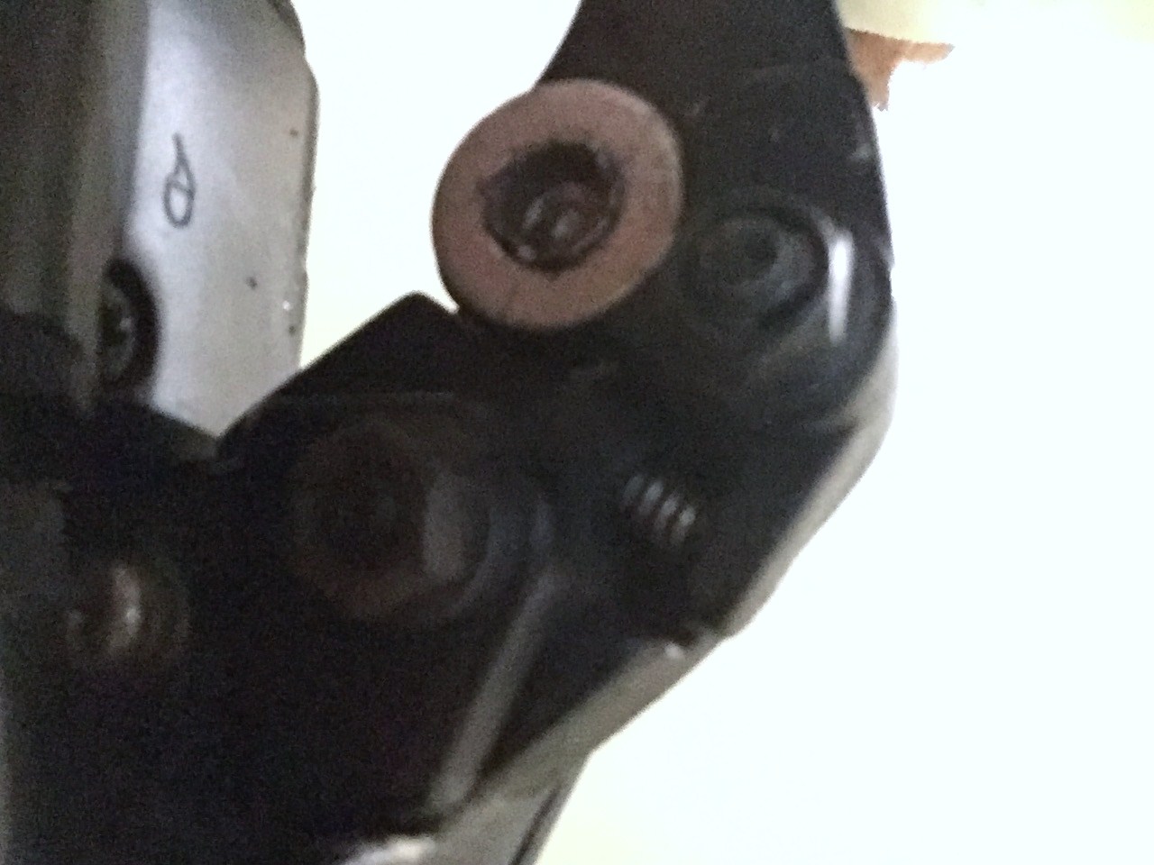
Here is a rather bad pic of the underside showing where the spring goes.
1982 KZ1000 LTD parts donor
1981 KZ1000 LTD awaiting resurrection
2000 ZRX1100 not ridden enough
www.kzrider.com/forum/11-projects/620336...amateur-build-thread
1981 KZ1000 LTD awaiting resurrection
2000 ZRX1100 not ridden enough
www.kzrider.com/forum/11-projects/620336...amateur-build-thread
The following user(s) said Thank You: davido
Please Log in or Create an account to join the conversation.
- davido
-
Topic Author
- Offline
- User
-
Registered
- Posts: 1580
- Thanks: 291
Re: CSR1000 Project Build
23 May 2016 22:32
Got it ! Thanks TexasKZ.
www.kzrider.com/forum/11-projects/594313-csr1000-project-build
CB550 (1978)
CB500/4 (1972)*
KZ1000CSR (1981)
XT 600E (1999)
TDM900 (2003)
CB550 (1978)
CB500/4 (1972)*
KZ1000CSR (1981)
XT 600E (1999)
TDM900 (2003)
Please Log in or Create an account to join the conversation.
Moderators: Street Fighter LTD