
Static Timing KZ1000A ?
- 650ed
-
- Offline
- User
-

Registered
- Posts: 15334
- Thanks: 2831
Re: Static Timing KZ1000A ?
15 Oct 2014 19:00
Then what is the problem?
1977 KZ650-C1 Original Owner - Stock (with additional invisible FIAMM horn)
Please Log in or Create an account to join the conversation.
- ezrider714
-

- Offline
- User
-
Registered
- Posts: 256
- Thanks: 38
Re: Static Timing KZ1000A ?
15 Oct 2014 19:06
kz The light should go out when the points are open, as well as the meter would not show continuity with the points open,there is none the gap between the points when open, breaks the continuity...
Your previous post stated the light would not go out???
Your tools are not an issue, for years my test light was an old tail light bulb from a 68 Chevy with 2 wires soldered on the contacts and 2 alligator clips on the other end.
Your previous post stated the light would not go out???
Your tools are not an issue, for years my test light was an old tail light bulb from a 68 Chevy with 2 wires soldered on the contacts and 2 alligator clips on the other end.
78 KZ650SR Mine since 79
4-1 Mac Jet Hot coated since mid 80's
Dyna Coils
Saddlebags (I ain't skeered of going nowhere)")
4-1 Mac Jet Hot coated since mid 80's
Dyna Coils
Saddlebags (I ain't skeered of going nowhere)
Please Log in or Create an account to join the conversation.
- kzdcw
-
 Topic Author
- Offline
- User
-
Registered
- 77' KZ1000A
- Posts: 857
- Thanks: 13
Re: Static Timing KZ1000A ?
15 Oct 2014 19:14
Ed, I really don't know. First off using the Test LIght, am I doing this test correctly?
I put a Charged Battery in the bike and hooked top both Battery Cables of the bike to it. Remember this is a Non-Running Bike that basically has all the wiring hooked up except ignition switch ( not plug into harness ), turn signals, and headlight/instrument wiring inside the headlight bucket. Don't know if this makes any difference or not?
The Test light required me to Clip it to the Pos. + ( Red ) Battery terminal to light up the Handle. The Pointer end of the handle I would touch the spring of the points I was attempting to adjust the timing. The F marks are aligned correctly. While continually touching the points spring with the pointer of the test light, the light stays on and never goes off while loosening the 2 timing screws and moving the plate or loosening the 3 back plate screws and moving the whole plate. What am I doing wrong?
The points 2 - wire Black/Green harness is unplugged at the coils.
77' KZ1000A
Please Log in or Create an account to join the conversation.
- 650ed
-
- Offline
- User
-
Registered
- Posts: 15334
- Thanks: 2831
Re: Static Timing KZ1000A ?
15 Oct 2014 19:17 - 15 Oct 2014 19:18
DO YOU HAVE AN ANALOG MULTI-METER; THE TYPE WITH A NEEDLE?
1977 KZ650-C1 Original Owner - Stock (with additional invisible FIAMM horn)
Last edit: 15 Oct 2014 19:18 by 650ed.
Please Log in or Create an account to join the conversation.
- 650ed
-
- Offline
- User
-
Registered
- Posts: 15334
- Thanks: 2831
Re: Static Timing KZ1000A ?
15 Oct 2014 19:19 - 15 Oct 2014 19:20
You are making this very simple task far too complicated.
If you use an analog multi-meter you do NOT need a battery at all in the bike. You do not need a key to the bike. The bike doesn't need to be operational at all. All you need is access to the points and the meter. Ed
If you use an analog multi-meter you do NOT need a battery at all in the bike. You do not need a key to the bike. The bike doesn't need to be operational at all. All you need is access to the points and the meter. Ed
1977 KZ650-C1 Original Owner - Stock (with additional invisible FIAMM horn)
Last edit: 15 Oct 2014 19:20 by 650ed.
Please Log in or Create an account to join the conversation.
- kzdcw
-
Topic Author
- Offline
- User
-
Registered
- 77' KZ1000A
- Posts: 857
- Thanks: 13
Re: Static Timing KZ1000A ?
15 Oct 2014 20:22 - 15 Oct 2014 20:27
Ed, I was trying to put off and ordering an Analog Meter and work with the tools that I have, but it appears to me I need to purchase one.
I agree, making this far to complicated. I just wish at least the Test Light would work the way it's supposed to?
Sorry, to cause frustration with everyone who answered this Post, but no one is more frustrated than me.
And to answer Eazyrider's question, the Light does go out when I Manually open the Points but Not when I loosen either the timing screws or back plate screws?
Now It is Correct once to Line up the F marks with the timing mark, you leave it there and just move the timing plate or back plate to see if the Meter moves or Light goes out?
77' KZ1000A
Last edit: 15 Oct 2014 20:27 by kzdcw.
Please Log in or Create an account to join the conversation.
- kzdcw
-
Topic Author
- Offline
- User
-
Registered
- 77' KZ1000A
- Posts: 857
- Thanks: 13
Re: Static Timing KZ1000A ?
15 Oct 2014 20:49
Patton or Ed, Can either of you show me how the 2 - wire Harness Green and Black coming from the Coils connects to the Points? I have the Clip ends of those 2 wires on the Top of the 2 insulators underneath the nut and lock washer? And I think that is the Problem ???
77' KZ1000A
Please Log in or Create an account to join the conversation.
- kzdcw
-
Topic Author
- Offline
- User
-
Registered
- 77' KZ1000A
- Posts: 857
- Thanks: 13
Re: Static Timing KZ1000A ?
15 Oct 2014 21:50
Wrong. Put the 2 coil wires Black and Green at the bottom where the Condenser wires are and made no difference at all?
Only way I can see how the Points would open even at all is as Patton says when the Raised Lobe of Advancer pushes against the Rubbing Block of the Points and there fore opens the Points.
Leaving The F mark alone once it's lined up properly ( Not rotating the 17mm Nut ) and Loosening up the 2 Timing Screws, the Timing plate once moved does not bring the Rubbing Blocks of the Points in contact with the Advancer? Therefore Not Opening up the Points ! I'm I thinking that I need a NEW set of Points?
77' KZ1000A
Please Log in or Create an account to join the conversation.
- 650ed
-
- Offline
- User
-
Registered
- Posts: 15334
- Thanks: 2831
Re: Static Timing KZ1000A ?
16 Oct 2014 05:15
The rubbing blocks should always be in contact with the little cam on the advancer regardless of the advancer's position. If that is not the case you have something wrong. One other thing you may want to check is the position of the little cam on the advancer unit. It is possible that someone installer the cam 180 degrees off. On the KZ650 advancer there is a little line on the cam that should approximately line up with a hole in the backplate (see image below). Yours may have similar marks. If the line is 180 degrees away from the hole remove the little cam by spreading the weights, turn it 180 degrees, and reinstall it. Ed
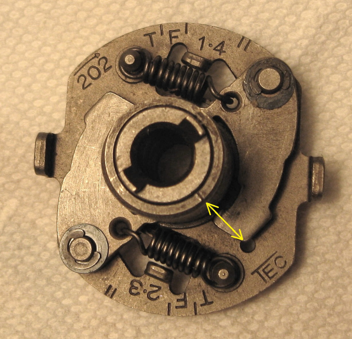
1977 KZ650-C1 Original Owner - Stock (with additional invisible FIAMM horn)
Please Log in or Create an account to join the conversation.
- 650ed
-
- Offline
- User
-
Registered
- Posts: 15334
- Thanks: 2831
Re: Static Timing KZ1000A ?
16 Oct 2014 05:20 - 16 Oct 2014 05:21kzdcw wrote: Patton or Ed, Can either of you show me how the 2 - wire Harness Green and Black coming from the Coils connects to the Points? I have the Clip ends of those 2 wires on the Top of the 2 insulators underneath the nut and lock washer? And I think that is the Problem ???
Again, you are making this far too complicated. You do NOT need to unhook any wires at the points.
Find the coils. They are under the fuel tank. You will see one has a green wire and one has a black wire. Each coil wire connects to a wire from the points. The coil wires connect to the points wires using bullet connectors. Disconnect the bullet connectors. That's all there is to it. Ed
1977 KZ650-C1 Original Owner - Stock (with additional invisible FIAMM horn)
Last edit: 16 Oct 2014 05:21 by 650ed.
Please Log in or Create an account to join the conversation.
- 650ed
-
- Offline
- User
-
Registered
- Posts: 15334
- Thanks: 2831
Re: Static Timing KZ1000A ?
16 Oct 2014 05:23
If you have disconnected the wires at the points or when you install new points here's how the wires, spring, and insulators should be arranged. Ed
Attachment PointsConnections.jpg not found
1977 KZ650-C1 Original Owner - Stock (with additional invisible FIAMM horn)
Please Log in or Create an account to join the conversation.
- kzdcw
-
Topic Author
- Offline
- User
-
Registered
- 77' KZ1000A
- Posts: 857
- Thanks: 13
Re: Static Timing KZ1000A ?
16 Oct 2014 11:40
Ed, Back art it again this morning. Incidentally when I'm disconnecting Black and Green wires going to the Coils, I do disconnect the Bullet connectors at the coils.
I pulled the whole Point Plate Assembly off as with the Advancer. Advancer is lined up Correctly with the line and Hole. I did notice at least to me, that the Cam Lobe of the advancer appears to be worn and not as smooth as I like to see. Seems likes there's light grooves on the surface I'm sure from wear. Don't know if that has anything to do with anything?
The Points I'm working with are Not new but appear to be in Good Shape. Insulators look good any not discolored and no pitting on the points contact surface.
I measured the Rubbing Block height that rides in the Cam. Measures 5.8-5.62mm. Have another set of much older points and they measure the same. I don't know what New Points measure but I guess if they were longer, it would definitely make contact with the Cam lobe of the Advancer?
Anyway, I examined everything on the Points Plate. All the insulators and wire connections are correct according to your diagram.Took everything apart including condenser and thoroughly cleaned points, condenser, plates, etc. Then reassembled.
Put Advancer in correctly and lined up Groove. Installed point plate assembly. Made sure No wires are touching Back plate. Re-adjusted Gap .014". Made sure points are opening and closing as they should be when rotating the motor clockwise.
Did the same adjustment/test to Statically Time it. Same Results as Yesterday.
You mentioned that the Rubbing Blocks of the Points are always in contact with the Cam? Mine are not. When attempting to Static Time cylinders 2 & 3 with the F Mark lined up with the pointer the rubbing block for the RIGHT points ( which is for 2 & 3 ) definitely Does Not make contact with the Cam lobe not matter which way you move the Timing plate or Back plate. Ironically the rubbing on the Left points ( 1 & 4 ) is making contact with the Cam Lobe but I'm sure that's the High spot on the Advancer cam.
I agree that an Analog Multimeter is probably the Right tool to use. But don't you think that the Test Light certainly should work especially when powering off the Battery and touching the point spring with the probe, I can Manually get the light to go Off when I open the points? It's just that the points are not opening up when moving the Plates therefore the Light stays on.
It would interesting to see what height the Rubbing Block measurement is? Maybe these Points are worn down so much they never make contact with the low side of the cam of the advancer.
Much, Much appreciate you taking the Time with me to Help work out this problem but Sorry we didn't accomplish anything. Any other Suggestions would be greatly appreciated!
77' KZ1000A
Please Log in or Create an account to join the conversation.
Moderators: Street Fighter LTD