
The Ongoing Chapters of the 650B2A.
- Johnbug
-
 Topic Author
- Offline
- User
-

Registered
- Posts: 48
- Thanks: 0
Re: The Ongoing Chapters of the 650B2A.
21 Apr 2017 09:59 - 21 Apr 2017 10:26
In fact if anyone would like to Skype and put input into this project in realtime I would greatly appreciate the extra input. Just shoot me a PM and I'll send my info.
Proud Confused Owner Of A KZ650B2A
Last edit: 21 Apr 2017 10:26 by Johnbug.
Please Log in or Create an account to join the conversation.
- KZB2 650
-

- Offline
- User
-
Registered
- Posts: 1472
- Thanks: 264
Re: The Ongoing Chapters of the 650B2A.
21 Apr 2017 10:23
By idle screws are you talking about the pilot screws that are located down below at the bowl area ? Also just so you know I was suggesting what the manual says to set the 24mm pilot screws at (1 and 1/8th turn and could be way off from what the 22s call for)
1978 KZ650 b-2
700cc Wiseco kit 10 to 1.
1980 KZ750 cam, ape springs, stock clutch/ Barnett springs.
Vance and Hines Header w/ comp baffle and Ape pods, Dyna S and green coils, copper wires.
29MM smooth bores W/ 17.5 pilots, 0-6s and 117.5 main
16/42 gearing X ring chain and alum rear JT sprocket.
700cc Wiseco kit 10 to 1.
1980 KZ750 cam, ape springs, stock clutch/ Barnett springs.
Vance and Hines Header w/ comp baffle and Ape pods, Dyna S and green coils, copper wires.
29MM smooth bores W/ 17.5 pilots, 0-6s and 117.5 main
16/42 gearing X ring chain and alum rear JT sprocket.
Please Log in or Create an account to join the conversation.
- Johnbug
-
Topic Author
- Offline
- User
-
Registered
- Posts: 48
- Thanks: 0
Re: The Ongoing Chapters of the 650B2A.
21 Apr 2017 10:29
Yes, sorry if my terminology is off but those are what I was referring to. At this point even if that may be way off it is worth a try. Since now it has a runaway idle anywhom.
Proud Confused Owner Of A KZ650B2A
Please Log in or Create an account to join the conversation.
- KZB2 650
-
- Offline
- User
-
Registered
- Posts: 1472
- Thanks: 264
Re: The Ongoing Chapters of the 650B2A.
21 Apr 2017 11:20
Hard to tell but that sure sounds rough....... hoping others sign in after hearing the vidio you just put up but have you done any cleaning of the carbs, adjust the cam chain, sync the carbs ....... its maybe a exhaust leak,sync or cam chain causing the banging I'm hearing ? Make sure the carb holder screws are tight when you remove the carbs again (still could be leaking even after) ........ I think you really need a factory manual to go over more than just carbs too.
1978 KZ650 b-2
700cc Wiseco kit 10 to 1.
1980 KZ750 cam, ape springs, stock clutch/ Barnett springs.
Vance and Hines Header w/ comp baffle and Ape pods, Dyna S and green coils, copper wires.
29MM smooth bores W/ 17.5 pilots, 0-6s and 117.5 main
16/42 gearing X ring chain and alum rear JT sprocket.
700cc Wiseco kit 10 to 1.
1980 KZ750 cam, ape springs, stock clutch/ Barnett springs.
Vance and Hines Header w/ comp baffle and Ape pods, Dyna S and green coils, copper wires.
29MM smooth bores W/ 17.5 pilots, 0-6s and 117.5 main
16/42 gearing X ring chain and alum rear JT sprocket.
The following user(s) said Thank You: GPz550D1
Please Log in or Create an account to join the conversation.
- Johnbug
-
Topic Author
- Offline
- User
-
Registered
- Posts: 48
- Thanks: 0
Re: The Ongoing Chapters of the 650B2A.
21 Apr 2017 11:47
There was an exhaust leak before. But after a repaint and some quick sanding and hammering there is no longer an exhaust leak. If there was you would see it on Cylinder 3s exhaust. As for the cam chain, I imagine that would be something needed to be done... That's not good at all if that's the issue...
Proud Confused Owner Of A KZ650B2A
Please Log in or Create an account to join the conversation.
- 650ed
-

- Offline
- User
-
Registered
- Posts: 15334
- Thanks: 2830
Re: The Ongoing Chapters of the 650B2A.
21 Apr 2017 12:08
I watched the video. If the engine was cold when you started it you didn't give it sufficient time to warm up to operating temperature before shutting it down. A cold KZ650 engine will take at least a couple minutes to warm up enough to shut off the choke. Until then the idle adjustment isn't worth fiddling with other than ensuring the bike isn't rev'ving up past 1500 rpm. After the engine is warmed up the idle can be adjusted to about 1,000 - 1,100 rpm, and after that is done you shouldn't need to fiddle with the idle adjustment screw any more. When the engine is cold and started with the choke on it will tend to idle high, but you control the idle by gradually turning off the choke as the engine warms up rather than turning the idle adjustment screw. Ed
1977 KZ650-C1 Original Owner - Stock (with additional invisible FIAMM horn)
The following user(s) said Thank You: GPz550D1
Please Log in or Create an account to join the conversation.
- Johnbug
-
Topic Author
- Offline
- User
-
Registered
- Posts: 48
- Thanks: 0
Re: The Ongoing Chapters of the 650B2A.
21 Apr 2017 13:30
A picture of the points.
Proud Confused Owner Of A KZ650B2A
Please Log in or Create an account to join the conversation.
- 650ed
-
- Offline
- User
-
Registered
- Posts: 15334
- Thanks: 2830
Re: The Ongoing Chapters of the 650B2A.
21 Apr 2017 13:38
Make sure the flat contact surfaces of the point are not pitted. If you need to adjust the point, or better yet when installing new points, the following may be helpful. It describes how I do the static points setting prior to final adjustment using a dwell meter and timing light.
The manual has several pages of instructions, pictures, etc. on how to set the timing using the static method plus timing light, plus dwell meter. I can give you a fairly easy way that will get you in a pretty close ballpark without a timing light or dwell meter, but you will need a 0.35 mm feeler gauge and a multi-meter or other device to test continuity. To be very precise, the timing light and dwell meter will be needed.
Before attempting to replace or adjust the points the following is important to understand; timing is comprised of two separate components, and BOTH of these components MUST be set properly if the engine is to run well:
--- The GAP - this is the distance the points spread apart when fully open. The GAP is the element that determines the DWELL. In essence, the DWELL is the number of degrees of points cam rotation that the points are closed and this controls the amount of time the coils receive a charge before firing the spark plugs.
--- The TIMING of the initial opening of the points (the point at which the continuity across the points breaks). This controls the precise instant that the coils receive the signal to fire the spark plugs.
Remove the points cover on the right side of engine. Under it you will see 2 sets of points. The set on the left fires cylinders 1 & 4; the set on the right fires 2 & 3. When replacing points observe carefully how the little bits and pieces are arranged where the wires attach. Some of those pieces are actually insulators and if you leave any of them out or put them back in the wrong place the points will be grounded and won't work. Take a very close look at the contact surfaces of the points. If they are pitted you really should replace them. You can sand down pitted points, but they will quickly pit again. Replace one set of points at a time so you can look at the other set in case you get the little bits confused.
Use a 17 mm wrench to turn the nut NEAR the end of the crankshaft clockwise while looking in the hole above that nut. (Do NOT use a wrench on the smaller bolt on the very end of the crankshaft to turn the engine.) Inside that hole you will see a vertical pointer cast into the casing. As you turn the 17 mm nut you will see a 1 & 4 and F and T roll by and then you'll see a 2 & 3 and F and T roll by. Each F and T has a line next to it.
Here's the method I use for static timing. I turn OFF the ignition. I disconnect the green wire near one coil and the black wire near the other coil. (This is not in the book, but it makes checking continuity much easier for me.) After installing the new points or cleaning up the old ones, turn the 17 mm nut while watching the points. When points set 1&4 are at their widest gap adjust them (by loosening the 2 screws that hold the points to the backplate) so the gap equals 0.35 mm. Turn the 17 mm nut clockwise through a full revolution again and double check this gap. Then repeat this for points set 2&3. Now set your meter to test continuity and clip one wire to the leaf spring on points set 1&4 and clip the other wire to ground. Turn the 17 mm nut clockwise until the 1&4 "F" mark aligns with the pointer mentioned above. You want the continuity across point set 1&4 to just break when the F mark aligns with the pointer. The idea is that when the continuity just fails is when the points will fire their respective coil and cylinders. In order to adjust the point at which continuity fails you loosen the 3 screws that hold the backplate to the engine and slightly turn the backplate until the meter shows a break in continuity. Once you have the 1&4 set timed properly you can check the 2&3 set to make sure they break when the 2&3 F mark aligns with the pointer (they should or something is not right). Don't forget to plug in the green and black coil wires when you are done, and put a little grease on the rubbing block felt. Assuming you are using new points of the correct type this should enable you to get the timing very close. Trying this with old points may give poor results, especially if the points are pitted and/or the rubbing blocks are worn.
After you have set the gap (which in effect sets the dwell) and the timing using the method above you can use a dwell meter and timing light to fine tune dwell and timing. If you have followed the above procedure carefully, very little if any fine tuning will be needed.
Sorry this is so long. It's not as difficult as it sounds. Ed
1977 KZ650-C1 Original Owner - Stock (with additional invisible FIAMM horn)
The following user(s) said Thank You: GPz550D1, Johnbug
Please Log in or Create an account to join the conversation.
- Johnbug
-
Topic Author
- Offline
- User
-
Registered
- Posts: 48
- Thanks: 0
Re: The Ongoing Chapters of the 650B2A.
21 Apr 2017 14:04
I cannot thank you enough for that explanation. I need to pick up a multimeter since all of mine are old and tempremental. I was looking in my book and it was not really all that helpful. Installed new Jet on carbs. 90 jets with 15 pilot. So its back to stock. As for the timing. I'll attempt that this evening. Here is a video of me rambling a bit from earlier that just finished uploading.
Proud Confused Owner Of A KZ650B2A
Please Log in or Create an account to join the conversation.
- 650ed
-
- Offline
- User
-
Registered
- Posts: 15334
- Thanks: 2830
Re: The Ongoing Chapters of the 650B2A.
21 Apr 2017 15:04
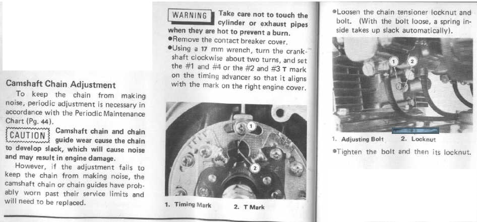
Before trying to adjust the cam chain tensioner be SURE to read how to adjust it (see below). The crankshaft MUST be turned to a specific position before trying to adjust it.
Also, the engine will be prone to idle roughly until a dynamic carb sync has been performed. The bench sync is a good starting point, but it assumes all cylinders are exactly the same. This is rarely true because there are several variables, such piston ring and valve condition differences, etc., that may cause the cylinders to pull slightly different vacuum. When the sync is off a little the engine can idle quite roughly. Another factor that will cause rough idle is minor vacuum leaks at the carb holders. I read that you found them to look like they're in good shape, but the only way to tell for sure is to test them becasue they will develop tiny hairline cracks at the mating surfaces which cannot be seen when they are on the engine. At the bottom of this reply is the test.
You should check the carb holders for leaks. They will eventually develop tiny cracks in the mating surfaces between the holders and the cylinder head that can cause them to leak at idle. These cracks cannot be seen with the carb holders in place. I suggest you try the following. Get the engine warmed up and temporarily set the idle as low as possible without killing the engine (lower than 900 rpm if possible). The lower the better because with the idle very low the slides are nearly shut and the vacuum inside the carb holders is at its highest. Then spray carb cleaner around the carb holders, especially where they mate with the cylinder head and where the carbs attach to them. Carb cleaner works best for this test as it doesn't leave an oily mess with WD40 or evaporate so quickly that it is not drawn into the leaks as can happen with propane or starting fluid (ether). If the engine dies or reacts to the carb cleaner, you need to replace the carb holders. Carb holder leak related problems are noticeable at idle but generally don't have much impact when riding because the throttle is open. If you find you need to replace the carb holders soak the screws with Kroil for a couple days before attempting to remove them, and use JIS standard, NOT Phillips, screwdriver bits, and this will greatly improve the odds that you will not break or strip a carb holder fastener as so many have done. Let me know if you need info on JIS bits, I have a good link for making your own at no cost.
Ed
1977 KZ650-C1 Original Owner - Stock (with additional invisible FIAMM horn)
Please Log in or Create an account to join the conversation.
- Johnbug
-
Topic Author
- Offline
- User
-
Registered
- Posts: 48
- Thanks: 0
Re: The Ongoing Chapters of the 650B2A.
21 Apr 2017 15:26 - 21 Apr 2017 15:30
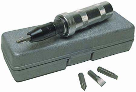
I actually created some JIS bits thanks to your first posts when I joined the forums ED. So again thank you. I picked up a multi meter and will attempt to set the points up correctly. Oh and to clear up a common theme, yes I do have a service manual for a KZ650B1. From 1977 to 1978. Its a Haynes manual and for most things I've found it pretty helpful. But when it comes to trouble shooting I find that the information provided by fellow forum members to be more accurate and helpful in the long run. Thank you for providing info on cam adjustment. I
Proud Confused Owner Of A KZ650B2A
Last edit: 21 Apr 2017 15:30 by Johnbug.
Please Log in or Create an account to join the conversation.
- SWest
-

- Offline
- Sustaining Member
-

Registered
- 10 22 2014
- Posts: 23693
- Thanks: 3001
Re: The Ongoing Chapters of the 650B2A.
21 Apr 2017 15:36 - 21 Apr 2017 15:36
I agree. A temporary fix it to use :ohmy: Permatex on the mating surfaces. I don't use it for ANYTHING else. Also a hand impact will take care of those stubborn bolts and screws.
Steve
Steve
Z1b1000 1975 Z1b
kzrider.com/forum/11-projects/598262-kz-...-will-it-live#672882
kzrider.com/forum/2-engine/597654-poser?start=240#704229
kzrider.com/forum/11-projects/598262-kz-...-will-it-live#672882
kzrider.com/forum/2-engine/597654-poser?start=240#704229
Last edit: 21 Apr 2017 15:36 by SWest.
Please Log in or Create an account to join the conversation.
Moderators: Street Fighter LTD