
testing charging system?
- davem
-
 Topic Author
- Offline
- User
-

Registered
- Posts: 86
- Thanks: 0
testing charging system?
19 Mar 2012 19:37Attachment wire3ohmtest.jpg not found
Attachment wire2ohmtest.jpg not found
Attachment vtestwithengineidleing.jpg not found
C:\fakepath\altornator output test..jpg
i tried to follow the directions in my manual for testing the charging syatem of my 1979 kz 1000 ltd
One of my problems is Im not sure if i am using my multi meter correctly and following the manuals inst. correctly.
I am attching pictures of what I did. Please instruct me if I did it correctly and what the diagnostics of the test revealed.
If I did it wrong please instruct me how to do it properly.
Thank you
Attachment alternatorstatorresistestinst.jpg not found
1979 Kz1000 B3 LTD
1997 Kawasaki police 1000
1985 kz1000p4 project-sold
1997 Kawasaki police 1000
1985 kz1000p4 project-sold
Attachments:
Please Log in or Create an account to join the conversation.
- davem
-
Topic Author
- Offline
- User
-
Registered
- Posts: 86
- Thanks: 0
Re: testing charging system?
19 Mar 2012 19:49 - 19 Mar 2012 19:53Attachment 2012-03-19_15-26-10_966.jpg not found
Attachment altornatoroutputtest.jpg not found
1979 Kz1000 B3 LTD
1997 Kawasaki police 1000
1985 kz1000p4 project-sold
1997 Kawasaki police 1000
1985 kz1000p4 project-sold
Attachments:
Last edit: 19 Mar 2012 19:53 by davem.
Please Log in or Create an account to join the conversation.
- davem
-
Topic Author
- Offline
- User
-
Registered
- Posts: 86
- Thanks: 0
Re: testing charging system?
19 Mar 2012 20:01
fTER DOMING THIS i REALIZED i PROBABLY COULD HAVE JUST DISCONNECTED THE CONNECTOR UNDER THE SIDE COVER. mY lTD HAS WHT THE INSTRUCTIONS SAY IS FOR THE SHAFT DRIVE.
1979 Kz1000 B3 LTD
1997 Kawasaki police 1000
1985 kz1000p4 project-sold
1997 Kawasaki police 1000
1985 kz1000p4 project-sold
Please Log in or Create an account to join the conversation.
- MFolks
-

- Offline
- User
-
Registered
- Posts: 6650
- Thanks: 541
Re: testing charging system?
19 Mar 2012 20:10
Alternator Testing For the Older 4’s(Z1’s,Kz 900’s, Kz1000’s,Kz1100’s ,GPz1100’s
And possibly the 750’s).
To check to see if the alternator is working you need to follow these simple steps:
1. Fully charge the battery as this will be the power source during this test.
2. Disconnect the Regulator/Rectifier at the plug that has the six wires in it.
3. Start the engine and let it warm to operating temperature.
4. If you're worried about overheating, position a large fan for cooling the engine.
5. After the engine has reached operating temperature, have a helper assist you, and using a multi-meter, read the output at the three yellow wires (or the alternator output wires)at the disconnected connector.
6. Raise the engine speed to 4000 rpm, and see what the three YELLOW wire combinations(or any alternator output wires) are(1-3, 2-3 & 1-2). The output will be around 50 Volts A.C.(Alternating Current). BE CAREFUL, AS THERE IS A SHOCK HAZARD HERE!!
7. If any of the combinations are low or non-existent, the stator(wire windings) are bad and must be replaced. Some of the older Z1’s and KZ900’s were reported to be phase sensitive, so check the wire colors carefully.
8. Using an OHMETER, Check the three wire combinations again, looking for a reading of 0.36 - 0.54 OHMS. If the readings are above or below, the stator may be bad and need replacement. Also check from any of the three YELLOW wires to ground, this will show if arcing took place. Check only with the engine off !!
9. Before ordering a new stator, check the connections from the stator as there are electrical "Bullet" connectors that may be damaged or dirty. Inspect the wiring for signs of shorting or overheating too. www.z1enterprises.com sells replacement rubber grommets for the alternator output wiring, they get hard and could leak oil after a while.
10. Check the wiring coming out of the grommet as there have been situations where the wires were damaged causing a short(I.E. twisted together with insulation damage).
11. The sprocket cover will have to be removed to access the electrical connectors coming from the alternator, the left foot peg assembly and shifting lever will have to come off also.
Alternator Stator Replacement On the Older 4’s
Source for replacement Stators
A. www.electrosport.com/technical-resources.../fault-finding-guide
B. www.customrewind.com
C. www.rmstator.com
D. www.regulatorrectifier.com
1. If by testing either by checking the output voltage from the stator or by using and ohmmeter for resistance and the stator is determined to be bad, replacing the stator is not a difficult job.
2. The motorcycle owner should have on hand a replacement alternator gasket as it will tear on removal and leak if reused.
3. Put the bike on the center stand if possible and lean it to the right to minimize the oil volume that could come out when the alternator cover is removed.
4. Have selection of Metric wrenches and sockets along with Metric Allen keys to be able to accomplish this repair. ¼" and 3/8" ratchets and extensions may be needed along with Allen bits.
5. Remove the gear shift lever, the sprocket cover and possibly the left foot peg assembly.
6. A catch pan for what little oil will be lost should be positioned under the alternator on the left side. Newspapers will soak up any oil lost or some kitty litter will do as an absorbent.
7. Remove the alternator cover fasteners, some bikes use a socket head cap screw(Allen type) and others use the Phillips head type, the #3 screwdriver bit fits best for those. Use a small dish or can to collect the removed fasteners from the parts to prevent loss/damage.
8. The alternator stator is secured to the inside of the cover usually with three Allen headed bolts, Some bikes may have Torx style fasteners, Remove them and disconnect the three yellow wires that have bullet connectors on them from the bundled wires inside the sprocket cover.
9. If your bike has some color other than yellow for the alternator output wires, make note of what goes where as the older Kawasaki’s were phase sensitive in regard to the regulator/rectifiers.
10. When installing the replacement stator, clock or position the output wires and grommet so they fit into the small port under the alternator cover without being pinched or damaged.
11. Tighten the three Allen or Torx fasteners, securing the replacement stator to the cover. I like using the BLUE Loctite # 242 for hardware that can be removed with hand tools.
12. Remove the old gasket from the mating surfaces of the alternator cover and engine case by scraping with a piece of sharpened plastic like Lexan or Plexi-glass as these will not gouge the soft Aluminum Cases. Avoid using a metal gasket scraper for this.
13. Position the alternator cover, checking for pinched wiring and install the fasteners with a little silver anti-seize on the threads, tightening to the correct torque.
14. Connect up the output wires to the mating female bullet connectors and while you’re in there, check the routing of the wire bundle that runs through there.
15. Inspect for signs of heat damage to the wire insulation and vibration damage too.
16. The side stand switch, neutral switch, and oil pressure switch wiring are all bundled with the alternator output wiring running above and behind the engine output sprocket. This bundle runs in a channel as it goes up toward the various electrical connections.
17. The regulator/rectifier plug on the 80’s bikes usually has six wires in it:
A. One (1)WHITE with RED stripe, this is the bikes main power wire usually 12 gauge in size.
B. One(1) smaller Brown wire, probably 18 gauge or so, the voltage sense wire for the regulator/rectifier, helps keeping it from overcharging the battery.
C. One(1) BLACK with YELLOW stripe wire, part of the ground circuits, maybe 16 gauge in size.
D. Three(3) YELLOW wires, maybe 14 gauge in size, the alternator output wires going to the regulator/rectifier which converts the Alternating Current(A.C.) to Direct Current(D.C.) using rectification, producing the power to run the motorcycle and charge the battery.
18. Reinstall the sprocket cover, again checking for pinched wires before tightening. Install the shifter on it’s splined shaft checking for proper location, and the left side foot peg assembly.
19. Except for the minor oil spill and reluctant fasteners, it’s not a very difficult job to do.
1982 GPZ1100 B2
General Dynamics/Convair 1983-1993
GLCM BGM-109 Tomahawk, AGM-129A Advanced Cruise Missile (ACM)
General Dynamics/Convair 1983-1993
GLCM BGM-109 Tomahawk, AGM-129A Advanced Cruise Missile (ACM)
Please Log in or Create an account to join the conversation.
- davem
-
Topic Author
- Offline
- User
-
Registered
- Posts: 86
- Thanks: 0
Re: testing charging system?
19 Mar 2012 20:34The batery was new and charged over night. I rode the bike to my shop about 10 minutes from my house and performed the test that I took pictures of.MFolks wrote: Alternator Testing For the Older 4’s(Z1’s,Kz 900’s, Kz1000’s,Kz1100’s ,GPz1100’s
And possibly the 750’s).
To check to see if the alternator is working you need to follow these simple steps:
1. Fully charge the battery as this will be the power source during this test.
2. Disconnect the Regulator/Rectifier at the plug that has the six wires in it.
3. Start the engine and let it warm to operating temperature.
4. If you're worried about overheating, position a large fan for cooling the engine.
5. After the engine has reached operating temperature, have a helper assist you, and using a multi-meter, read the output at the three yellow wires (or the alternator output wires)at the disconnected connector.
6. Raise the engine speed to 4000 rpm, and see what the three YELLOW wire combinations(or any alternator output wires) are(1-3, 2-3 & 1-2). The output will be around 50 Volts A.C.(Alternating Current). BE CAREFUL, AS THERE IS A SHOCK HAZARD HERE!!
7. If any of the combinations are low or non-existent, the stator(wire windings) are bad and must be replaced. Some of the older Z1’s and KZ900’s were reported to be phase sensitive, so check the wire colors carefully.
8. Using an OHMETER, Check the three wire combinations again, looking for a reading of 0.36 - 0.54 OHMS. If the readings are above or below, the stator may be bad and need replacement. Also check from any of the three YELLOW wires to ground, this will show if arcing took place. Check only with the engine off !!
9. Before ordering a new stator, check the connections from the stator as there are electrical "Bullet" connectors that may be damaged or dirty. Inspect the wiring for signs of shorting or overheating too. www.z1enterprises.com sells replacement rubber grommets for the alternator output wiring, they get hard and could leak oil after a while.
10. Check the wiring coming out of the grommet as there have been situations where the wires were damaged causing a short(I.E. twisted together with insulation damage).
11. The sprocket cover will have to be removed to access the electrical connectors coming from the alternator, the left foot peg assembly and shifting lever will have to come off also.
Alternator Stator Replacement On the Older 4’s
Source for replacement Stators
A. www.electrosport.com/technical-resources.../fault-finding-guide
B. www.customrewind.com
C. www.rmstator.com
D. www.regulatorrectifier.com
1. If by testing either by checking the output voltage from the stator or by using and ohmmeter for resistance and the stator is determined to be bad, replacing the stator is not a difficult job.
2. The motorcycle owner should have on hand a replacement alternator gasket as it will tear on removal and leak if reused.
3. Put the bike on the center stand if possible and lean it to the right to minimize the oil volume that could come out when the alternator cover is removed.
4. Have selection of Metric wrenches and sockets along with Metric Allen keys to be able to accomplish this repair. ¼" and 3/8" ratchets and extensions may be needed along with Allen bits.
5. Remove the gear shift lever, the sprocket cover and possibly the left foot peg assembly.
6. A catch pan for what little oil will be lost should be positioned under the alternator on the left side. Newspapers will soak up any oil lost or some kitty litter will do as an absorbent.
7. Remove the alternator cover fasteners, some bikes use a socket head cap screw(Allen type) and others use the Phillips head type, the #3 screwdriver bit fits best for those. Use a small dish or can to collect the removed fasteners from the parts to prevent loss/damage.
8. The alternator stator is secured to the inside of the cover usually with three Allen headed bolts, Some bikes may have Torx style fasteners, Remove them and disconnect the three yellow wires that have bullet connectors on them from the bundled wires inside the sprocket cover.
9. If your bike has some color other than yellow for the alternator output wires, make note of what goes where as the older Kawasaki’s were phase sensitive in regard to the regulator/rectifiers.
10. When installing the replacement stator, clock or position the output wires and grommet so they fit into the small port under the alternator cover without being pinched or damaged.
11. Tighten the three Allen or Torx fasteners, securing the replacement stator to the cover. I like using the BLUE Loctite # 242 for hardware that can be removed with hand tools.
12. Remove the old gasket from the mating surfaces of the alternator cover and engine case by scraping with a piece of sharpened plastic like Lexan or Plexi-glass as these will not gouge the soft Aluminum Cases. Avoid using a metal gasket scraper for this.
13. Position the alternator cover, checking for pinched wiring and install the fasteners with a little silver anti-seize on the threads, tightening to the correct torque.
14. Connect up the output wires to the mating female bullet connectors and while you’re in there, check the routing of the wire bundle that runs through there.
15. Inspect for signs of heat damage to the wire insulation and vibration damage too.
16. The side stand switch, neutral switch, and oil pressure switch wiring are all bundled with the alternator output wiring running above and behind the engine output sprocket. This bundle runs in a channel as it goes up toward the various electrical connections.
17. The regulator/rectifier plug on the 80’s bikes usually has six wires in it:
A. One (1)WHITE with RED stripe, this is the bikes main power wire usually 12 gauge in size.
B. One(1) smaller Brown wire, probably 18 gauge or so, the voltage sense wire for the regulator/rectifier, helps keeping it from overcharging the battery.
C. One(1) BLACK with YELLOW stripe wire, part of the ground circuits, maybe 16 gauge in size.
D. Three(3) YELLOW wires, maybe 14 gauge in size, the alternator output wires going to the regulator/rectifier which converts the Alternating Current(A.C.) to Direct Current(D.C.) using rectification, producing the power to run the motorcycle and charge the battery.
18. Reinstall the sprocket cover, again checking for pinched wires before tightening. Install the shifter on it’s splined shaft checking for proper location, and the left side foot peg assembly.
19. Except for the minor oil spill and reluctant fasteners, it’s not a very difficult job to do.
Did I have the meter set correctly? Did I do the test correctly based on my pictures?
1979 Kz1000 B3 LTD
1997 Kawasaki police 1000
1985 kz1000p4 project-sold
1997 Kawasaki police 1000
1985 kz1000p4 project-sold
Please Log in or Create an account to join the conversation.
- KraZy Chris
-
- Offline
- User
-
Registered
- Posts: 95
- Thanks: 0
Re: testing charging system?
19 Mar 2012 21:15
When the instructions say to test resistance set your meter to the one that looks like an upside down horseshoe when testing voltage use DC volts (DCV). Be careful resistance measurements have to be made without power or you may ruin your meter
78 KZ1000, Middle TN
Please Log in or Create an account to join the conversation.
- Old Man Rock
-
- Offline
- User
-
Registered
- Posts: 6074
- Thanks: 225
Re: testing charging system?
20 Mar 2012 09:04 - 20 Mar 2012 09:07
First image VAC measurement...
Is it me or am I seeing this correctly where you have the following terminations.
* Red probe to white alligator clip connected to single phase, ok....
* Black probe is not grounded where still in your hand.... :blink:
If seeing this correctly, equates to no worky in Vac measurements....
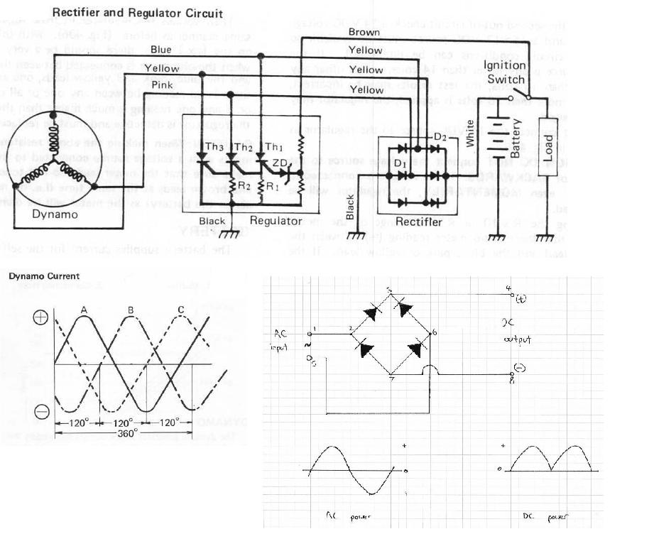
With engine running at idle, in measuring any of the yellow conductors in reference to ground, one third (3 phase) of Vac total should be measured (~ 20-25Vac). If connected across any two yellow pairs, measurements of 2/3rds of total Vac should me displayed (~ 50Vac as per your manuals depiction)...
Maybe this will help...
Granted this is for my KZ9000 & Early KZ1000 but the theory still applies.
Is it me or am I seeing this correctly where you have the following terminations.
* Red probe to white alligator clip connected to single phase, ok....
* Black probe is not grounded where still in your hand.... :blink:
If seeing this correctly, equates to no worky in Vac measurements....
With engine running at idle, in measuring any of the yellow conductors in reference to ground, one third (3 phase) of Vac total should be measured (~ 20-25Vac). If connected across any two yellow pairs, measurements of 2/3rds of total Vac should me displayed (~ 50Vac as per your manuals depiction)...
Maybe this will help...
Granted this is for my KZ9000 & Early KZ1000 but the theory still applies.
1976 KZ900-A4
MTC 1075cc.
Camshafts: Kawi GPZ-1100 .375 lift
Head: P&P via Larry Cavanaugh
ZX636 suspension
MIKUNI, RS-34'S...
Kerker 4-1, 1.5" comp baffle.
Dyna-S E.I.
Earls 10 row Oil Cooler
Acewell 2802 Series Speedo/Tach
Innovate LC1 Wideband 02 AFR meter
Phoenix, Az
MTC 1075cc.
Camshafts: Kawi GPZ-1100 .375 lift
Head: P&P via Larry Cavanaugh
ZX636 suspension
MIKUNI, RS-34'S...
Kerker 4-1, 1.5" comp baffle.
Dyna-S E.I.
Earls 10 row Oil Cooler
Acewell 2802 Series Speedo/Tach
Innovate LC1 Wideband 02 AFR meter
Phoenix, Az
Attachments:
Last edit: 20 Mar 2012 09:07 by Old Man Rock.
Please Log in or Create an account to join the conversation.
- Motor Head
-

- Offline
- User
-
Registered
- FIX UP YOUR BIKE RIGHT AND CHEAP
- Posts: 5137
- Thanks: 393
Re: testing charging system?
20 Mar 2012 10:39
Put your meter on ACV and measure at the Yellow wires from the stator, any combination of the three. Each should be about 50 ACV. This is using each of the test leads, one to each of the three yellows and the other to another yellow. Run the motor up to 4K RPM. If all three combinations measure above 50 ACv then the stator should be OK.
Do this first to find out if the Stator is good. Look closely at the condition of these three yellow wires along the harness to see if any of the wires look heat damaged, stiff, discolored, etc. You may want to replace the section of wire from the stator to the Regulator/ Rectifier if it is suspect.
The Brown wire at the R/R needs to see battery voltage, but switched on with the key. So if you measure the battery, across the posts, Voltage DC this time, the Brown wire should be the same at Key On. If it measures much less, than you have resistance in your connections causing voltage drop. This will lead to an Overcharge issue. The battery will boil, and be ruined. So get the Stator checked, then proceed from there.
1982 KZ1000LTD K2 Vance & Hines 4-1 ACCEL COILS Added Vetter fairing & Bags. FOX Racing rear Shocks, Braced Swing-arm, Fork Brace, Progressive Fork Springs RT Gold Emulators, APE Valve Springs, 1166 Big Bore kit, RS34's, GPZ cams.
1980 KZ550LTD C1 Stock SOLD Miss it
1979 MAZDA RX7 in the works, 13B...
1980 KZ550LTD C1 Stock SOLD Miss it
1979 MAZDA RX7 in the works, 13B...
Please Log in or Create an account to join the conversation.
- davem
-
Topic Author
- Offline
- User
-
Registered
- Posts: 86
- Thanks: 0
Re: testing charging system?
20 Mar 2012 17:35Ok ....i think i did the tests right.Motor Head wrote: Put your meter on ACV and measure at the Yellow wires from the stator, any combination of the three. Each should be about 50 ACV. This is using each of the test leads, one to each of the three yellows and the other to another yellow. Run the motor up to 4K RPM. If all three combinations measure above 50 ACv then the stator should be OK.
Do this first to find out if the Stator is good. Look closely at the condition of these three yellow wires along the harness to see if any of the wires look heat damaged, stiff, discolored, etc. You may want to replace the section of wire from the stator to the Regulator/ Rectifier if it is suspect.
The Brown wire at the R/R needs to see battery voltage, but switched on with the key. So if you measure the battery, across the posts, Voltage DC this time, the Brown wire should be the same at Key On. If it measures much less, than you have resistance in your connections causing voltage drop. This will lead to an Overcharge issue. The battery will boil, and be ruined. So get the Stator checked, then proceed from there.
Volts at battery across post key off 11.5v
Key on measure across battery post is 6v
key on test brown wire an ground connector coming from stator 6v
Engine on with stator plug connected to the rr plug vots across terminals 10.5
Yellow wires....
55 55 60 @4000 rpms
Whats the diagnostics?
1979 Kz1000 B3 LTD
1997 Kawasaki police 1000
1985 kz1000p4 project-sold
1997 Kawasaki police 1000
1985 kz1000p4 project-sold
Please Log in or Create an account to join the conversation.
- Patton
-

- Offline
- KZr Legend
-

Registered
- Posts: 18568
- Thanks: 2102
Re: testing charging system?
20 Mar 2012 18:30
Battery voltage measured across posts should be:
12+ volts, engine not running, ignition switch ON or OFF;
13+ volts at idle rpm;
14+ volts at 3000~4000 rpm.
Too high indicates possible regulator malfunction.
Too low indicates possible alternator and/or rectifier malfunction.
Good Fortune!")
12+ volts, engine not running, ignition switch ON or OFF;
13+ volts at idle rpm;
14+ volts at 3000~4000 rpm.
Too high indicates possible regulator malfunction.
Too low indicates possible alternator and/or rectifier malfunction.
Good Fortune!
1973 Z1
KZ900 LTD
KZ900 LTD
Please Log in or Create an account to join the conversation.
- davem
-
Topic Author
- Offline
- User
-
Registered
- Posts: 86
- Thanks: 0
Re: testing charging system?
20 Mar 2012 18:41Patton wrote: Battery voltage measured across posts should be:
12+ volts, engine not running, ignition switch ON or OFF;
13+ volts at idle rpm;
14+ volts at 3000~4000 rpm.
Too high indicates possible regulator malfunction.
Too low indicates possible alternator and/or rectifier malfunction.
Good Fortune!
So im trying not to throw parts at this untill im sure...
is it possible that i still have a wiring issue?
Another thing i just noticed is
I have no low beam headlight and no rear running(orange) lights. Fuses are all good
1979 Kz1000 B3 LTD
1997 Kawasaki police 1000
1985 kz1000p4 project-sold
1997 Kawasaki police 1000
1985 kz1000p4 project-sold
Please Log in or Create an account to join the conversation.
- Patton
-
- Offline
- KZr Legend
-
Registered
- Posts: 18568
- Thanks: 2102
Re: testing charging system?
20 Mar 2012 18:48 - 20 Mar 2012 18:49 Will the engine run well enough to obtain voltage measurements across the battery posts at idle and at 3000~4000 rpm? And if so, what are the readings?
Good Fortune!
1973 Z1
KZ900 LTD
KZ900 LTD
Last edit: 20 Mar 2012 18:49 by Patton.
Please Log in or Create an account to join the conversation.
Moderators: Street Fighter LTD