
KZ bottom end assembly
- joehooper
-
 Topic Author
- Offline
- User
-

Vendors
- Posts: 16
- Thanks: 39
KZ bottom end assembly
14 Mar 2017 12:50 - 15 Mar 2017 07:04
Pit Stop Performance instructions for
Z1, KZ900, KZ1000 & KZ1100
All models 1973 - 2005
Bottom End Assembly
Last updated 3/14/2017
Here is how you start.
Clean and prep for assembly:
Clean the two case halves using mineral spirits or equivalent. If you have access to a Safety Kleen tank, that is even better.
Remove the cleaning solvent with soapy water. I like to use Dawn dish washing detergent.
Remove the soapy water by rinsing with a garden hose.
Finally blow the cases dry using compressed air.
Be sure to blow out every threaded bolt hole, there are a bunch of them.
Clean all bolts following the same procedure above. Wire wheel the threaded portion of all the bolts.
Finally, before installation lubricate the threads of every bolt with oil.
Turn top case upside down on bench, sitting on the cylinder studs and the top rear motor mount.
Rules to follow:
There are a few things you should do all the time.
Any time a bolt is installed, the threads and the shoulder of the bolt should be lubricated with oil. There are two reasons for this. First, it allows for the applied torque to be correct. Without lubrication, the applied torque can vary widely from the intended value. Second is to prevent damage due to scoring of the threads on either the bolt or the threaded bolt hole. Lubricating the shoulder of the bolt accomplishes the same purpose in that spot.
Any time an o’ring is installed, the entire o’ring should be coated with a thin layer of oil. Put a few drops on two opposing fingers and pull the o’ring through until the entire surface is coated.
The only time any force is required is when mating two parts that have dowel pins. The crankshaft and transmission shafts us solid dowel pins and they do not require and force and should just drop in when properly aligned. The dowel pins that mate the cases and secure some of the covers are a very snug fit as they are intended to hold the parts in an exact location.
Here is a helpful hint that we use to install covers and gaskets. Cut the head off of several 6mm bolts. You can use them to install in the case and center the gasket before installing the cover. This works particularly well if you are installing gasket sealer on the cover gaskets as you can line up all the bolt holes before the gasket makes contact with the sealer.
Install crankshaft and main bearing cap:
Verify that there are six main bearing outer race locating solid dowel pins, one in each crankshaft main bearing saddle in the top case. The dowel pins are 6mm X 14mm they are solid and heat treated.
Install the cam chain on the crankshaft. Use a 122 pin roller cam chain for a crankshaft with a 15 tooth crank sprocket (Z1/A/B KZ900A4/A5/B1 KZ1000A1/A2/A2A/B1-B3/C1/C1A/C2/D1) and a 124 pin roller cam chain for a crankshaft with a 16 tooth crank sprocket (KZ1000A3/A3A/A4/B4/C3/C4/D3/E1/E2). There are some 1979 Mark II motors I have come across that do not have a 124 pin cam chain. If in doubt, count the teeth on the crankshaft or the camshaft sprockets to be sure. In order to use the 124 pin cam chain, the motor must have a 16 tooth crankshaft sprocket and 32 tooth camshaft sprockets. For use on a 1981 and later model (KZ1000J1/J2/J3/K1/K2/M1/M2/P1-P21/R1/R2 KZ1100A1-A3/B1/B2/D1/D2/L1 ZN1100B1/B2 ZX1100A1/A2) with a Hy-Vo chain, use a 152 pin Hy-Vo cam chain.
Gently place the crankshaft in the upper case. Verify the the crankshaft is in the correct direction. The longer end of the crankshaft (with the charging system rotor) goes on the dyno cover side of the case, the short end of the crankshaft goes on the ignition side of the case.
Start at one end of the crankshaft and rotate each bearing outer race until you feel it fall into place on the locating dowel pin.
Before going any further, look at the outer bearing race on each side of the case and verify that it is down as far as it can go in the upper case.
Install the main bearing cap with the arrow pointing toward the front of the motor, verify that it is seated solidly against the case.
There are a total of twelve 8mm shouldered bolts in the motor. They come in three different lengths as follows:
(") 72mm (2.83”)
72mm (2.83”)
(2) 81mm (3.19”)
(2) 95mm (3.74”)
The main bearing cap uses (4) of the shortest bolts (72mm). Oil the threads and shoulder and install these bolts. Torque the bearing cap bolts using a 12mm socket in three steps of 10 foot pounds (120 inch pounds), 14 foot pounds (168 inch pounds) and finally 18 foot pounds (216 inch pounds). Tighten the bolts in a pattern crossing from one corner to the other. Check the final torque twice. Verify the crankshaft will rotate smoothly back and forth.
Install transmission input shaft and clutch outer basket:
Verify that there is a main bearing outer race locating solid dowel pin in the small bearing race of the transmission input shaft.
The dowel pin is 6mm X 14mm.
Verify that there is a locating ring for the large diameter bearing in the groove in the upper case.
Install the transmission input shaft by holding it above the crankshaft and engage the gear at the bottom of the clutch basket with the drive gear on the crankshaft. Rotate the input shaft down until it is seated in the case. Be sure to engage the locating ring on the large diameter bearing, it positions the bearing in the case by engaging in a groove in the bearing and another in the upper case. Be sure the ends of the locating ring are below the mating surface of the case. The outer race of the small bearing needs to be rotated until the hole in the outer race engages with the dowel pin. Verify both bearings are firmly seated in the upper case. Rock the clutch basket back and forth and verify the transmission input shaft and crankshaft rotate smoothly.
Install transmission output shaft:
Verify that there is a main bearing outer race solid dowel pin in the small bearing race of the transmission output shaft.
The dowel pin is 6mm X 14mm.
Verify that there is a locating ring for the large diameter bearing in the groove in the upper case.
Install the transmission output shaft by holding it above the input shaft and engaging all the gears between input and output shafts. Rotate the output shaft down until it is seated in the case. Be sure to engage the locating ring on the large diameter bearing, it positions the bearing in the case by engaging in a groove in the bearing and another in the upper case. Be sure the ends of the locating ring are below the mating surface of the case. The outer race of the small bearing needs to be rotated until the hole in the outer race engages with the dowel pin. Verify both bearings are firmly seated in the upper case. Rock the transmission output shaft back and forth just a little and verify smooth rotation. If you rotate the transmission too far at this point, you can cause the input or output shaft to lift out of the case.
Install kickstarter shaft:
This step is not required for on a 1981 and later model (KZ1000J1/J2/J3/K1/K2/M1/M2/P1-P21/R1/R2 KZ1100A1-A3/B1/B2/D1/D2/L1 ZN1100B1/B2 ZX1100A1/A2) with a Hy-Vo chain.
Verify that there is a main bearing outer race solid dowel pin in the small bearing race of the kickstarter shaft.
Install the kickstarter shaft by engaging it’s gear to the transmission gear and rotating it down into place in the case. Position the ratchet pawl straight up. Rotate bearing race until the hole in the collar outer race is engaged in the dowel pin. Rotate the shaft clockwise until the ratchet pawl just contacts the stopper plate bolted to the upper case. Do not rotate any part of the transmission further until the cases are bolted together.
Install bottom case:
Coat the mating surfaces of both the top and bottom cases with a thin layer of Three Bond liquid gasket 1184.
Look at the bearing outer races of both transmission shafts and the kickstarter shaft (1973-1980). Verify that all of the outer races are seated all the way in the upper case.
Veriy there are two case locating dowels in either the top case or the bottom case. One is located at the front of the case and the other at the back.
Lubricate and install (1) 92055-048 O’ring in the oil port between the two case halves. The O’ring has a “D” shaped cross section. The flat side of the D goes into the O’ring relief cutout.
Verify the oil relief valve is installed in the lower case half.
Install the bottom case onto the top case by gently lowering it into place. If the shift drum and fork are installed in the bottom case, engage the shift fork on the fourth/fifth slider gear before lowering the bottom case all the way. A rubber mallet may be used directly above the case dowel pins to push the cases together. Verify the case is very close to touching all around before installing bolts.
Install and torque case bolts:
The bolts to bolt the cases together are all shouldered bolts and consist of the following bolts going in from the bottom of the case:
(4) 8mm X 72mm (2.83”) long
(2) 8mm X 81mm (3.18”) long
(2) 8mm X 95mm (3.74”) long
(10) 6mm X 41mm (1.61”) long
(4) 6mm X 94mm (3.70”) long
(2) 6mm X 54mm (2.12”) long
(1) 6mm X 72mm (2.83”) long (1973 – 1980 only)
The following bolts go in from the top of the case:
(2) 6mm X 41mm (1.61”) long
(1) 6mm X 54mm (2.12”) long
(1) 6mm X 99mm (3.89”) long
(1) 6mm X 116mm (4.57”) long
Apply oil on the threads and shoulder of each bolt before installation.
Put the 8mm bolts in first. The four 8mm X 72mm long bolts go inside of the oil pan. The two 8mm X 81mm long bolts go outside the oil pan on the ignition side and the remaining two 8mm X 95mm long bolts go outside the oil pan on the dyno side.
Torque the 8mm case bolts in three steps of 10 foot pounds (120 inch pounds), 14 foot pounds (168 inch pounds) and finally 18 foot pounds (216 inch pounds). Perform torque in the order of the numbers 1 through 8 that appear on the bottom of the case. Check the final torque twice.
Next install the 6mm bolts. Oil the thread and shoulder of all bolts. Install all the bolts before tightening any of them. With the case upside down and the back of the motor closest to you install bolts as follows:
(4) 6mm X 94mm bolts go in on the left side starting just behind the crankshaft.
(1) 6mm X 72mm bolt (1973-1980) goes to the left of the last 6mm X 94mm bolt between the kickstarter and the back of the motor.
(2) 6mm X 54mm bolts in the 1973-1980 motor, these go in the bolt holes that have the dowel pins. In the 1981 and later motor, the front one goes in the hole with the dowel pin, the other dowel pin does not have a bolt in it, the bolt in the back goes on the rear most row on the left side (working with the motor upside down and the back facing you).
(10) 6mm X 41mm bolts go in the remaining empty holes.
Note that there is one less 6mm case bolt on a 1981 and later motor. That is because there is no kickstarter shaft and the case is a little simpler. Torque the 6mm case bolts in two steps of 50 inch pounds and 70 inch pounds. Perform torque starting at any bolt and going around in a counter clockwise direction. Check the final torque twice. Lubricate and install the two shift forks and the shaft that supports them.
Install kickstarter return spring and cover:
This step is not required on a 1981 and later model (KZ1000J1/J2/J3/K1/K2/M1/M2/P1-P21/R1/R2 KZ1100A1-A3/B1/B2/D1/D2/L1 ZN1100B1/B2 ZX1100A1/A2) with a Hy-Vo chain.
Rotate kickstarter shaft clockwise as far as it will go. Install kickstarter spring by holding spring with needle nose pliers. Put the long straight end into the hole in the case. Rotate the spring counter clockwise until the short end of the spring can be engaged into the hole in the kickstarter shaft. Install the kickstarter spring guide by sliding over the kickstarter shaft. Verify there are two dowel pins in the two forward holes either in the case or the kickstarter cover. Lubricate the inside of the kick starter cover seal and install the kickstarter cover gasket and cover. A rubber mallet may be used to force it down on the dowel pins.
Install (2) 6mm X 25mm (.98”) phillips head screw in the dowel I n hoes and (2) 6mm X 40mm (1.57”) phillips head screw in the remaining holes, torque snug.
Install transmission cover:
Install shifter mechanism with spring and overshift bushing (if in use).
Verify two dowel pins either in cover or in cases.
Install transmission cover gasket on the dowel pins.
Lubricate all three seals and install cover.
Install the following bolts and torque snug:
(5) 6mm X 22mm (.86”) phillips head screw
(1) 6mm X 28mm (1.09”) phillips head screw
(2) 6mm X 40mm (1.56”) phillips head screw
(1) 6mm X 56mm (2.20”) phillips head screw
The transmission should be rotated and shifted through all gears several times.
Before turning the motor over, remove (or verify removed) both dowel pins for the oil pump. This will allow the motor to have a perfectly flat surface to sit on when it is turned over.
Turn the motor over, oil the thread and shoulder of all bolts and install the remaining five bolts:
(2) 6mm X 41mm (1.61”) long hex head bolt
(1) 6mm X 54mm (2.12”) long hex head bolt
(1) 6mm X 99mm (3.89”) long hex head bolt
(1) 6mm X 116mm (4.57”) long hex head bolt
The (2)41mm bolts along with the 54mm bolt go under the starter motor. The remaining 99mm and 116mm bolts go on the high ridge of the case near the counter shaft sprocket cover mating surface. Torque the 6mm case bolts in two steps of 50 inch pounds and 70 inch pounds.
Install starter motor:
Verify the snout of the starter motor has a good 92055-1276 24mm o’ring installed. A drop of oil applied to the o’ring will make installation easier. Install the starter motor and secure it with two 6mm X 56mm (2.22”) long bolts and two 6mm flat washers. As always, oil the bolt threads before installation. Torque the 6mm starter motor bolts in two steps of 50 inch pounds and 70 inch pounds.
Assemble clutch and install cover:
Examine all eight of the clutch friction discs for cracks or unusual wear.
Replace as required.
Bead blast the metal plates if required.
Lubricate both the friction discs and the metal plates and install. Start with a friction disc, then a metal plate. Alternate until complete. There are eight friction discs and seven metal plates on 1973 models and nine frictions discs and eight metal plates on 1981 and later models. The last one installed will be a friction disc.
Install the 3/8” steel clutch pusher ball in the shaft (1973-1980 models) and then install the clutch pusher.
Next install the pressure plate and clutch springs, secure it with:
(5) 6mm X 18mm hex head bolts with large washers.
There are some models, drive shaft in particular that have six bolts securing the pressure plate. They are allen head and have washers with a recessed face.
Torque to 70 inch pounds (snug).
Install the clutch cover gasket and clutch cover, secure with:
(9) 6mm X 25mm (.988”) long phillips head screws
Tighten snug.
Install ignition and housing:
Verify two dowel pins installed, one top and one bottom either in the case or the points base. Lubricate seal and install gasket and points base, a rubber mallet may be used to force it down on the dowel pins. Install (6) 6mm X 22mm (.866”) long phillips head screw, torque snug.
Verify there is one small dowel pin on the crankshaft end.
Install the ignition timing advancer using one 17mm nut and one 8mm bolt. Torque to 12 foot pounds. The easiest method of torquing both the dyno bolt and the ignition advancer bolt is to perform the torqueing operations together. Use a wrench on the dyno bolt to prevent the crankshaft from rotating and torque the 13mm bolt on the ignition advancer. Then use a 17mm wrench on the ignition advancer to prevent rotation and torque the dyno bolt.
Install ignition timing plate using (3) 5mm X 12mm phillips head screw with lock washer and flat washer, torque snug.
Install points cover using (2) 6mm X 40mm phillips head screw, torque snug.
Install alternator rotor and alternator cover:
Place copper washer with four grooves, bevel to the inside on the crankshaft end, followed by the caged needle bearing assembly.
Next is a large rubber damper. It is a large steel and rubber washer with a recess on one side. Put grease on the flat side and attach it to the back of the starter clutch gear. If a half moon key is in use (1973-1978), rotate the crankshaft until the keyway is up and install the key. Install the alternator rotor and starter clutch assembly onto the end of the crankshaft. Be sure to engage the key if in use.
Install alternator rotor bolt. Torque to 18 foot pounds (1973-1978) or 80 foot pounds (1979 and later). The easiest method of torqueing both the dyno bolt and the ignition advancer bolt is to perform the torqueing operations together. Use a wrench on the dyno bolt to prevent the crankshaft from rotating and torque the 13mm bolt on the ignition advancer. Then use a 17mm wrench on the ignition advancer to prevent rotation and torque the dyno bolt.
Install the starter idler gear and shaft.
Verify two dowel pins either in cover or cases. Install dyno cover gasket and install cover, secure cover with:
(6) 6mm X 30mm (1.18”) phillips head screw
(2) 6mm X 40mm (1.57”) phillips head screw
Tighten snug.
Install oil pipe:
On 1973 to 1980 models, install the oil pipe using:
(2) 18mm o’ring part number 670B2018
(4) 6mm X 35mm (1.38”) hex head shouldered bolt (some also have phillips notches)
Oil bolt thread and shoulder, install and torque to 70 in pounds.
On 1981 and later models, install the oil pipe using:
(2) 22mm o’ring part number 670B2022
(2) 8mm bolt
Oil bolt thread and shoulder, install and torque to 150 inch pounds.
Install crank case breather:
Install crankcase breather using:
(1)o’ring 92055-052
(1)o’ring 670B2016
(1)shouldered bolt with breather hole
When top case assembly is complete, proceed to oil pump and oil pan installation:
Turn motor upside down.
Oil pump installation:
Verify two dowel pins installed in pump or bottom case.
Lubricate and install (1) 92055-048 D-shaped cross section o’ring in the pump oil passage.
Install the pump and press it down onto the dowel pins.
Lubricate threads and shoulders and install the following bolts:
(1)6mm X 22mm (.87”) long shouldered hex head bolt or hex head bolt with flat washer
(1)6mm X 35mm (1.38”) long shouldered hex head bolt or hex head bolt with flat washer
(1)6mm X 45mm (1.77”) long shouldered hex head bolt or hex head bolt with flat washer
Torque bolts to 70 in pounds.
Oil pan installation:
Install (1)92055-052 o’ring into the goove in the oil pan. A few dabs of grease may be used to hold it in place.
Install the oil pan gasket and the oil pan.
Secure the pan with:
(13)6mm X 25mm (.98”) long hex head bolt
(3)6mm X 34mm (1.34”) long hex head bolt
(1)6mm X 48mm (1.89”) longhex head bolt
Torque bolts to 70 in pounds.
Oil filter installation:
If your oil filter came with the two o’rings, dissassemble the cover/bolt assembly and install a new o’ring on the bolt.
Lubricate the o’ring and install the bolt in the cover.
Install the filter spring, the filter washer and finally the filter.
Install the large cover o’ring. A few dabs of grease may be used to hold it in place.
Install the filter/cover assembly.
Tighten snug.
The first comments I expect to get are that the torque specifications do not match the factory specifications. If you prefer to use the factory specs, please feel free to do so. My specifications are based on the fact that most of these motors are in the vicinity of 40 years old. Some of my specs are lower than the factory manual because I have had to repair thousands of damaged bolt holes.
You should now be ready for the top end installation. You can install the bottom end into the chassis, or if you have and engine stand you can install that and then turn the motor over on your bench for top end installation. Installing the bottom end into the chassis without the top end installed is much easier than instlling a completely assembled motor. However, that is up to you.
Additionally, if you plan to degree your camshafts, you will want to wait to install the starter idler gear and the dyno cover until after that is complete.
This procedure assumes a lot of things and it not intended to assemble every part of the motor. It assumes, for instance, that the transmission is already assembled and the clutch basket is attached to the input shaft. On 1981 and later motors, the clutch basket can be installed after the cases are assembled. I will let someone else provide that procedure.
Z1, KZ900, KZ1000 & KZ1100
All models 1973 - 2005
Bottom End Assembly
Last updated 3/14/2017
Here is how you start.
Clean and prep for assembly:
Clean the two case halves using mineral spirits or equivalent. If you have access to a Safety Kleen tank, that is even better.
Remove the cleaning solvent with soapy water. I like to use Dawn dish washing detergent.
Remove the soapy water by rinsing with a garden hose.
Finally blow the cases dry using compressed air.
Be sure to blow out every threaded bolt hole, there are a bunch of them.
Clean all bolts following the same procedure above. Wire wheel the threaded portion of all the bolts.
Finally, before installation lubricate the threads of every bolt with oil.
Turn top case upside down on bench, sitting on the cylinder studs and the top rear motor mount.
Rules to follow:
There are a few things you should do all the time.
Any time a bolt is installed, the threads and the shoulder of the bolt should be lubricated with oil. There are two reasons for this. First, it allows for the applied torque to be correct. Without lubrication, the applied torque can vary widely from the intended value. Second is to prevent damage due to scoring of the threads on either the bolt or the threaded bolt hole. Lubricating the shoulder of the bolt accomplishes the same purpose in that spot.
Any time an o’ring is installed, the entire o’ring should be coated with a thin layer of oil. Put a few drops on two opposing fingers and pull the o’ring through until the entire surface is coated.
The only time any force is required is when mating two parts that have dowel pins. The crankshaft and transmission shafts us solid dowel pins and they do not require and force and should just drop in when properly aligned. The dowel pins that mate the cases and secure some of the covers are a very snug fit as they are intended to hold the parts in an exact location.
Here is a helpful hint that we use to install covers and gaskets. Cut the head off of several 6mm bolts. You can use them to install in the case and center the gasket before installing the cover. This works particularly well if you are installing gasket sealer on the cover gaskets as you can line up all the bolt holes before the gasket makes contact with the sealer.
Install crankshaft and main bearing cap:
Verify that there are six main bearing outer race locating solid dowel pins, one in each crankshaft main bearing saddle in the top case. The dowel pins are 6mm X 14mm they are solid and heat treated.
Install the cam chain on the crankshaft. Use a 122 pin roller cam chain for a crankshaft with a 15 tooth crank sprocket (Z1/A/B KZ900A4/A5/B1 KZ1000A1/A2/A2A/B1-B3/C1/C1A/C2/D1) and a 124 pin roller cam chain for a crankshaft with a 16 tooth crank sprocket (KZ1000A3/A3A/A4/B4/C3/C4/D3/E1/E2). There are some 1979 Mark II motors I have come across that do not have a 124 pin cam chain. If in doubt, count the teeth on the crankshaft or the camshaft sprockets to be sure. In order to use the 124 pin cam chain, the motor must have a 16 tooth crankshaft sprocket and 32 tooth camshaft sprockets. For use on a 1981 and later model (KZ1000J1/J2/J3/K1/K2/M1/M2/P1-P21/R1/R2 KZ1100A1-A3/B1/B2/D1/D2/L1 ZN1100B1/B2 ZX1100A1/A2) with a Hy-Vo chain, use a 152 pin Hy-Vo cam chain.
Gently place the crankshaft in the upper case. Verify the the crankshaft is in the correct direction. The longer end of the crankshaft (with the charging system rotor) goes on the dyno cover side of the case, the short end of the crankshaft goes on the ignition side of the case.
Start at one end of the crankshaft and rotate each bearing outer race until you feel it fall into place on the locating dowel pin.
Before going any further, look at the outer bearing race on each side of the case and verify that it is down as far as it can go in the upper case.
Install the main bearing cap with the arrow pointing toward the front of the motor, verify that it is seated solidly against the case.
There are a total of twelve 8mm shouldered bolts in the motor. They come in three different lengths as follows:
(
72mm (2.83”)(2) 81mm (3.19”)
(2) 95mm (3.74”)
The main bearing cap uses (4) of the shortest bolts (72mm). Oil the threads and shoulder and install these bolts. Torque the bearing cap bolts using a 12mm socket in three steps of 10 foot pounds (120 inch pounds), 14 foot pounds (168 inch pounds) and finally 18 foot pounds (216 inch pounds). Tighten the bolts in a pattern crossing from one corner to the other. Check the final torque twice. Verify the crankshaft will rotate smoothly back and forth.
Install transmission input shaft and clutch outer basket:
Verify that there is a main bearing outer race locating solid dowel pin in the small bearing race of the transmission input shaft.
The dowel pin is 6mm X 14mm.
Verify that there is a locating ring for the large diameter bearing in the groove in the upper case.
Install the transmission input shaft by holding it above the crankshaft and engage the gear at the bottom of the clutch basket with the drive gear on the crankshaft. Rotate the input shaft down until it is seated in the case. Be sure to engage the locating ring on the large diameter bearing, it positions the bearing in the case by engaging in a groove in the bearing and another in the upper case. Be sure the ends of the locating ring are below the mating surface of the case. The outer race of the small bearing needs to be rotated until the hole in the outer race engages with the dowel pin. Verify both bearings are firmly seated in the upper case. Rock the clutch basket back and forth and verify the transmission input shaft and crankshaft rotate smoothly.
Install transmission output shaft:
Verify that there is a main bearing outer race solid dowel pin in the small bearing race of the transmission output shaft.
The dowel pin is 6mm X 14mm.
Verify that there is a locating ring for the large diameter bearing in the groove in the upper case.
Install the transmission output shaft by holding it above the input shaft and engaging all the gears between input and output shafts. Rotate the output shaft down until it is seated in the case. Be sure to engage the locating ring on the large diameter bearing, it positions the bearing in the case by engaging in a groove in the bearing and another in the upper case. Be sure the ends of the locating ring are below the mating surface of the case. The outer race of the small bearing needs to be rotated until the hole in the outer race engages with the dowel pin. Verify both bearings are firmly seated in the upper case. Rock the transmission output shaft back and forth just a little and verify smooth rotation. If you rotate the transmission too far at this point, you can cause the input or output shaft to lift out of the case.
Install kickstarter shaft:
This step is not required for on a 1981 and later model (KZ1000J1/J2/J3/K1/K2/M1/M2/P1-P21/R1/R2 KZ1100A1-A3/B1/B2/D1/D2/L1 ZN1100B1/B2 ZX1100A1/A2) with a Hy-Vo chain.
Verify that there is a main bearing outer race solid dowel pin in the small bearing race of the kickstarter shaft.
Install the kickstarter shaft by engaging it’s gear to the transmission gear and rotating it down into place in the case. Position the ratchet pawl straight up. Rotate bearing race until the hole in the collar outer race is engaged in the dowel pin. Rotate the shaft clockwise until the ratchet pawl just contacts the stopper plate bolted to the upper case. Do not rotate any part of the transmission further until the cases are bolted together.
Install bottom case:
Coat the mating surfaces of both the top and bottom cases with a thin layer of Three Bond liquid gasket 1184.
Look at the bearing outer races of both transmission shafts and the kickstarter shaft (1973-1980). Verify that all of the outer races are seated all the way in the upper case.
Veriy there are two case locating dowels in either the top case or the bottom case. One is located at the front of the case and the other at the back.
Lubricate and install (1) 92055-048 O’ring in the oil port between the two case halves. The O’ring has a “D” shaped cross section. The flat side of the D goes into the O’ring relief cutout.
Verify the oil relief valve is installed in the lower case half.
Install the bottom case onto the top case by gently lowering it into place. If the shift drum and fork are installed in the bottom case, engage the shift fork on the fourth/fifth slider gear before lowering the bottom case all the way. A rubber mallet may be used directly above the case dowel pins to push the cases together. Verify the case is very close to touching all around before installing bolts.
Install and torque case bolts:
The bolts to bolt the cases together are all shouldered bolts and consist of the following bolts going in from the bottom of the case:
(4) 8mm X 72mm (2.83”) long
(2) 8mm X 81mm (3.18”) long
(2) 8mm X 95mm (3.74”) long
(10) 6mm X 41mm (1.61”) long
(4) 6mm X 94mm (3.70”) long
(2) 6mm X 54mm (2.12”) long
(1) 6mm X 72mm (2.83”) long (1973 – 1980 only)
The following bolts go in from the top of the case:
(2) 6mm X 41mm (1.61”) long
(1) 6mm X 54mm (2.12”) long
(1) 6mm X 99mm (3.89”) long
(1) 6mm X 116mm (4.57”) long
Apply oil on the threads and shoulder of each bolt before installation.
Put the 8mm bolts in first. The four 8mm X 72mm long bolts go inside of the oil pan. The two 8mm X 81mm long bolts go outside the oil pan on the ignition side and the remaining two 8mm X 95mm long bolts go outside the oil pan on the dyno side.
Torque the 8mm case bolts in three steps of 10 foot pounds (120 inch pounds), 14 foot pounds (168 inch pounds) and finally 18 foot pounds (216 inch pounds). Perform torque in the order of the numbers 1 through 8 that appear on the bottom of the case. Check the final torque twice.
Next install the 6mm bolts. Oil the thread and shoulder of all bolts. Install all the bolts before tightening any of them. With the case upside down and the back of the motor closest to you install bolts as follows:
(4) 6mm X 94mm bolts go in on the left side starting just behind the crankshaft.
(1) 6mm X 72mm bolt (1973-1980) goes to the left of the last 6mm X 94mm bolt between the kickstarter and the back of the motor.
(2) 6mm X 54mm bolts in the 1973-1980 motor, these go in the bolt holes that have the dowel pins. In the 1981 and later motor, the front one goes in the hole with the dowel pin, the other dowel pin does not have a bolt in it, the bolt in the back goes on the rear most row on the left side (working with the motor upside down and the back facing you).
(10) 6mm X 41mm bolts go in the remaining empty holes.
Note that there is one less 6mm case bolt on a 1981 and later motor. That is because there is no kickstarter shaft and the case is a little simpler. Torque the 6mm case bolts in two steps of 50 inch pounds and 70 inch pounds. Perform torque starting at any bolt and going around in a counter clockwise direction. Check the final torque twice. Lubricate and install the two shift forks and the shaft that supports them.
Install kickstarter return spring and cover:
This step is not required on a 1981 and later model (KZ1000J1/J2/J3/K1/K2/M1/M2/P1-P21/R1/R2 KZ1100A1-A3/B1/B2/D1/D2/L1 ZN1100B1/B2 ZX1100A1/A2) with a Hy-Vo chain.
Rotate kickstarter shaft clockwise as far as it will go. Install kickstarter spring by holding spring with needle nose pliers. Put the long straight end into the hole in the case. Rotate the spring counter clockwise until the short end of the spring can be engaged into the hole in the kickstarter shaft. Install the kickstarter spring guide by sliding over the kickstarter shaft. Verify there are two dowel pins in the two forward holes either in the case or the kickstarter cover. Lubricate the inside of the kick starter cover seal and install the kickstarter cover gasket and cover. A rubber mallet may be used to force it down on the dowel pins.
Install (2) 6mm X 25mm (.98”) phillips head screw in the dowel I n hoes and (2) 6mm X 40mm (1.57”) phillips head screw in the remaining holes, torque snug.
Install transmission cover:
Install shifter mechanism with spring and overshift bushing (if in use).
Verify two dowel pins either in cover or in cases.
Install transmission cover gasket on the dowel pins.
Lubricate all three seals and install cover.
Install the following bolts and torque snug:
(5) 6mm X 22mm (.86”) phillips head screw
(1) 6mm X 28mm (1.09”) phillips head screw
(2) 6mm X 40mm (1.56”) phillips head screw
(1) 6mm X 56mm (2.20”) phillips head screw
The transmission should be rotated and shifted through all gears several times.
Before turning the motor over, remove (or verify removed) both dowel pins for the oil pump. This will allow the motor to have a perfectly flat surface to sit on when it is turned over.
Turn the motor over, oil the thread and shoulder of all bolts and install the remaining five bolts:
(2) 6mm X 41mm (1.61”) long hex head bolt
(1) 6mm X 54mm (2.12”) long hex head bolt
(1) 6mm X 99mm (3.89”) long hex head bolt
(1) 6mm X 116mm (4.57”) long hex head bolt
The (2)41mm bolts along with the 54mm bolt go under the starter motor. The remaining 99mm and 116mm bolts go on the high ridge of the case near the counter shaft sprocket cover mating surface. Torque the 6mm case bolts in two steps of 50 inch pounds and 70 inch pounds.
Install starter motor:
Verify the snout of the starter motor has a good 92055-1276 24mm o’ring installed. A drop of oil applied to the o’ring will make installation easier. Install the starter motor and secure it with two 6mm X 56mm (2.22”) long bolts and two 6mm flat washers. As always, oil the bolt threads before installation. Torque the 6mm starter motor bolts in two steps of 50 inch pounds and 70 inch pounds.
Assemble clutch and install cover:
Examine all eight of the clutch friction discs for cracks or unusual wear.
Replace as required.
Bead blast the metal plates if required.
Lubricate both the friction discs and the metal plates and install. Start with a friction disc, then a metal plate. Alternate until complete. There are eight friction discs and seven metal plates on 1973 models and nine frictions discs and eight metal plates on 1981 and later models. The last one installed will be a friction disc.
Install the 3/8” steel clutch pusher ball in the shaft (1973-1980 models) and then install the clutch pusher.
Next install the pressure plate and clutch springs, secure it with:
(5) 6mm X 18mm hex head bolts with large washers.
There are some models, drive shaft in particular that have six bolts securing the pressure plate. They are allen head and have washers with a recessed face.
Torque to 70 inch pounds (snug).
Install the clutch cover gasket and clutch cover, secure with:
(9) 6mm X 25mm (.988”) long phillips head screws
Tighten snug.
Install ignition and housing:
Verify two dowel pins installed, one top and one bottom either in the case or the points base. Lubricate seal and install gasket and points base, a rubber mallet may be used to force it down on the dowel pins. Install (6) 6mm X 22mm (.866”) long phillips head screw, torque snug.
Verify there is one small dowel pin on the crankshaft end.
Install the ignition timing advancer using one 17mm nut and one 8mm bolt. Torque to 12 foot pounds. The easiest method of torquing both the dyno bolt and the ignition advancer bolt is to perform the torqueing operations together. Use a wrench on the dyno bolt to prevent the crankshaft from rotating and torque the 13mm bolt on the ignition advancer. Then use a 17mm wrench on the ignition advancer to prevent rotation and torque the dyno bolt.
Install ignition timing plate using (3) 5mm X 12mm phillips head screw with lock washer and flat washer, torque snug.
Install points cover using (2) 6mm X 40mm phillips head screw, torque snug.
Install alternator rotor and alternator cover:
Place copper washer with four grooves, bevel to the inside on the crankshaft end, followed by the caged needle bearing assembly.
Next is a large rubber damper. It is a large steel and rubber washer with a recess on one side. Put grease on the flat side and attach it to the back of the starter clutch gear. If a half moon key is in use (1973-1978), rotate the crankshaft until the keyway is up and install the key. Install the alternator rotor and starter clutch assembly onto the end of the crankshaft. Be sure to engage the key if in use.
Install alternator rotor bolt. Torque to 18 foot pounds (1973-1978) or 80 foot pounds (1979 and later). The easiest method of torqueing both the dyno bolt and the ignition advancer bolt is to perform the torqueing operations together. Use a wrench on the dyno bolt to prevent the crankshaft from rotating and torque the 13mm bolt on the ignition advancer. Then use a 17mm wrench on the ignition advancer to prevent rotation and torque the dyno bolt.
Install the starter idler gear and shaft.
Verify two dowel pins either in cover or cases. Install dyno cover gasket and install cover, secure cover with:
(6) 6mm X 30mm (1.18”) phillips head screw
(2) 6mm X 40mm (1.57”) phillips head screw
Tighten snug.
Install oil pipe:
On 1973 to 1980 models, install the oil pipe using:
(2) 18mm o’ring part number 670B2018
(4) 6mm X 35mm (1.38”) hex head shouldered bolt (some also have phillips notches)
Oil bolt thread and shoulder, install and torque to 70 in pounds.
On 1981 and later models, install the oil pipe using:
(2) 22mm o’ring part number 670B2022
(2) 8mm bolt
Oil bolt thread and shoulder, install and torque to 150 inch pounds.
Install crank case breather:
Install crankcase breather using:
(1)o’ring 92055-052
(1)o’ring 670B2016
(1)shouldered bolt with breather hole
When top case assembly is complete, proceed to oil pump and oil pan installation:
Turn motor upside down.
Oil pump installation:
Verify two dowel pins installed in pump or bottom case.
Lubricate and install (1) 92055-048 D-shaped cross section o’ring in the pump oil passage.
Install the pump and press it down onto the dowel pins.
Lubricate threads and shoulders and install the following bolts:
(1)6mm X 22mm (.87”) long shouldered hex head bolt or hex head bolt with flat washer
(1)6mm X 35mm (1.38”) long shouldered hex head bolt or hex head bolt with flat washer
(1)6mm X 45mm (1.77”) long shouldered hex head bolt or hex head bolt with flat washer
Torque bolts to 70 in pounds.
Oil pan installation:
Install (1)92055-052 o’ring into the goove in the oil pan. A few dabs of grease may be used to hold it in place.
Install the oil pan gasket and the oil pan.
Secure the pan with:
(13)6mm X 25mm (.98”) long hex head bolt
(3)6mm X 34mm (1.34”) long hex head bolt
(1)6mm X 48mm (1.89”) longhex head bolt
Torque bolts to 70 in pounds.
Oil filter installation:
If your oil filter came with the two o’rings, dissassemble the cover/bolt assembly and install a new o’ring on the bolt.
Lubricate the o’ring and install the bolt in the cover.
Install the filter spring, the filter washer and finally the filter.
Install the large cover o’ring. A few dabs of grease may be used to hold it in place.
Install the filter/cover assembly.
Tighten snug.
The first comments I expect to get are that the torque specifications do not match the factory specifications. If you prefer to use the factory specs, please feel free to do so. My specifications are based on the fact that most of these motors are in the vicinity of 40 years old. Some of my specs are lower than the factory manual because I have had to repair thousands of damaged bolt holes.
You should now be ready for the top end installation. You can install the bottom end into the chassis, or if you have and engine stand you can install that and then turn the motor over on your bench for top end installation. Installing the bottom end into the chassis without the top end installed is much easier than instlling a completely assembled motor. However, that is up to you.
Additionally, if you plan to degree your camshafts, you will want to wait to install the starter idler gear and the dyno cover until after that is complete.
This procedure assumes a lot of things and it not intended to assemble every part of the motor. It assumes, for instance, that the transmission is already assembled and the clutch basket is attached to the input shaft. On 1981 and later motors, the clutch basket can be installed after the cases are assembled. I will let someone else provide that procedure.
Last edit: 15 Mar 2017 07:04 by KZQ.
The following user(s) said Thank You: GPz550D1, 531blackbanshee, DOHC, MDZ1rider, Street Fighter LTD, SWest
Please Log in or Create an account to join the conversation.
- 650ed
-

- Offline
- User
-
Registered
- Posts: 15334
- Thanks: 2830
Re: KZ bottom end assembly
14 Mar 2017 13:07 - 15 Mar 2017 07:04
Now I'm confused.
You state: "Any time a bolt is installed, the threads and the shoulder of the bolt should be lubricated with oil. There are two reasons for this. First, it allows for the applied torque to be correct. Without lubrication, the applied torque can vary widely from the intended value. Second is to prevent damage due to scoring of the threads on either the bolt or the threaded bolt hole. Lubricating the shoulder of the bolt accomplishes the same purpose in that spot."
But the Kawasaki Service Manual States:
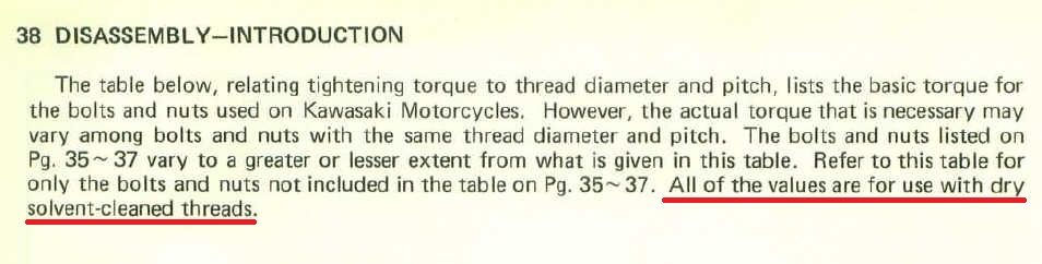
Can you help me understand the discrepancy?
Thanks,
Ed
You state: "Any time a bolt is installed, the threads and the shoulder of the bolt should be lubricated with oil. There are two reasons for this. First, it allows for the applied torque to be correct. Without lubrication, the applied torque can vary widely from the intended value. Second is to prevent damage due to scoring of the threads on either the bolt or the threaded bolt hole. Lubricating the shoulder of the bolt accomplishes the same purpose in that spot."
But the Kawasaki Service Manual States:
Can you help me understand the discrepancy?
Thanks,
Ed
1977 KZ650-C1 Original Owner - Stock (with additional invisible FIAMM horn)
Last edit: 15 Mar 2017 07:04 by KZQ.
Please Log in or Create an account to join the conversation.
- joehooper
-
Topic Author
- Offline
- User
-
Vendors
- Posts: 16
- Thanks: 39
Re: KZ bottom end assembly
14 Mar 2017 14:08 - 15 Mar 2017 07:05
Ed
Like I said, if you want to use the manual, feel free.
My procedure is based on 43 years of experience and hundreds of motors assembled.
I never said that any other procedure is wrong, I am just offering mine.
The use of these instructions is up to the user.
Like I said, if you want to use the manual, feel free.
My procedure is based on 43 years of experience and hundreds of motors assembled.
I never said that any other procedure is wrong, I am just offering mine.
The use of these instructions is up to the user.
Last edit: 15 Mar 2017 07:05 by KZQ.
The following user(s) said Thank You: KZQ, GPz550D1, Street Fighter LTD
Please Log in or Create an account to join the conversation.
- rrsmsw9999
-

- Offline
- User
-
Registered
- Posts: 775
- Thanks: 65
Re: KZ bottom end assembly
14 Mar 2017 14:15 - 15 Mar 2017 07:05
I would not oil the bolts. They will be over torque if FSM specs are followed. You procedure is very thorough otherwise. The case bolts and fasteners over 6mm will likely not have a problem with over torque (10 to 15% when wet), any smaller could strip the aluminium threads. R
1980 KZ 1000E2
Crashed 6/2016
1980 KZ550A
Sold 3/2016
Crashed 6/2016
1980 KZ550A
Sold 3/2016
Last edit: 15 Mar 2017 07:05 by KZQ.
Please Log in or Create an account to join the conversation.
- 650ed
-
- Offline
- User
-
Registered
- Posts: 15334
- Thanks: 2830
Re: KZ bottom end assembly
14 Mar 2017 14:19 - 15 Mar 2017 07:05
joehooper wrote: "Ed - Like I said, if you want to use the manual, feel free.
My procedure is based on 43 years of experience and hundreds of motors assembled.
I never said that any other procedure is wrong, I am just offering mine.
The use of these instructions is up to the user. "
I don't at all doubt the success you've had using your method, and your method may be considerably better than that described in the manual. I was only trying to understand if there was an explanation as to the different approaches.
Maybe there is a difference in the torque values used. Do you use the torque tables from the manuals or some other reference? Also, do you tend to torque to the low, middle, or high end of the torque ranges specified?
Thanks,
Ed
1977 KZ650-C1 Original Owner - Stock (with additional invisible FIAMM horn)
Last edit: 15 Mar 2017 07:05 by KZQ.
Please Log in or Create an account to join the conversation.
- Nebr_Rex
-

- Offline
- User
-
Registered
- Posts: 1889
- Thanks: 295
Re: KZ bottom end assembly
15 Mar 2017 03:11 - 15 Mar 2017 07:05
Anybody who doesn't believe torqued bolts should not be lubricated has not worked with stainless steel hardware.
.
.
2002 ZRX1200R
81 GPz1100
79 KZ1000st daily ride
79 KZ1000mk2 prodject
78 KZ650sr
78 KZ650b
81 KZ750e
80 KZ750ltd
77 KZ400/440 cafe project
76 KZ400/440 Fuel Injected
www.dotheton.com/index.php?threads/dr-je...air-of-kz400s.39120/
.
81 GPz1100
79 KZ1000st daily ride
79 KZ1000mk2 prodject
78 KZ650sr
78 KZ650b
81 KZ750e
80 KZ750ltd
77 KZ400/440 cafe project
76 KZ400/440 Fuel Injected
www.dotheton.com/index.php?threads/dr-je...air-of-kz400s.39120/
.
Last edit: 15 Mar 2017 07:05 by KZQ.
Please Log in or Create an account to join the conversation.
- rrsmsw9999
-
- Offline
- User
-
Registered
- Posts: 775
- Thanks: 65
Re: KZ bottom end assembly
15 Mar 2017 03:35 - 15 Mar 2017 07:05
Not sure what you mean. Regardless of material you will have to alter torque values by -10-15% if you use lubed hardware. These Kaw bikes have pretty soft aluminum. Steel or SS will strip the aluminum threads with too much torque. Lube em all ya want if you compensate for torque or eventually the smaller fasteners will be stripped. I know plenty of folks that never use a torque wrench with fine results, but I rely of proper measures of torque when I work on a motor. 2 each their own. R
1980 KZ 1000E2
Crashed 6/2016
1980 KZ550A
Sold 3/2016
Crashed 6/2016
1980 KZ550A
Sold 3/2016
Last edit: 15 Mar 2017 07:05 by KZQ.
Please Log in or Create an account to join the conversation.
- LarryC
-
- Offline
- User
-
Registered
- Posts: 1241
- Thanks: 309
Re: KZ bottom end assembly
15 Mar 2017 05:07 - 15 Mar 2017 07:06
The only thing I would suggest as an addition to this topic would be to toss the 8mm crank bolts, stock cylinder studs, head nuts and washers in the trash. I replace that old crap with heavy duty fasteners on every engine I build from the bottom up.
I have had the 8mm crank bolts snap off during tear down. Why run the risk of having one snap during assembly.
I have had the 8mm crank bolts snap off during tear down. Why run the risk of having one snap during assembly.
Larry C.
Last edit: 15 Mar 2017 07:06 by KZQ.
The following user(s) said Thank You: SWest
Please Log in or Create an account to join the conversation.
- SWest
-

- Offline
- Sustaining Member
-

Registered
- 10 22 2014
- Posts: 23688
- Thanks: 3001
Re: KZ bottom end assembly
15 Mar 2017 06:36 - 15 Mar 2017 07:06
Just had that happen to me. I wish I had used anti seize at least when I put it together in 13.
Steve
Steve
Z1b1000 1975 Z1b
kzrider.com/forum/11-projects/598262-kz-...-will-it-live#672882
kzrider.com/forum/2-engine/597654-poser?start=240#704229
kzrider.com/forum/11-projects/598262-kz-...-will-it-live#672882
kzrider.com/forum/2-engine/597654-poser?start=240#704229
Last edit: 15 Mar 2017 07:06 by KZQ.
The following user(s) said Thank You: GPz550D1
Please Log in or Create an account to join the conversation.
- flyv
-

- Offline
- User
-
Registered
- Posts: 4
- Thanks: 4
Re: KZ bottom end assembly
16 Mar 2017 19:30
I just finished assembling my engine this week. I would also recommend neverseize on everything. Taking it apart I broke one of the crankcase bolts and one of the small 10MM bolts. Tried mig weding washer and nut, tried heat and finally drilled and retapped both.
I wish i would of read the post earlier as I had to remove the oil pan to see why the kickstarter was not disengaging. Finally figured that when the arm on the bendix is bottomed out on the stop, that is when the return spring is installed with the tension on it. interesting enough the reason I split the cases was to replace the stop for the kickstarter. it had broken off the tab and i can not figure how this can ever be possible. I think the previous owner may have realized something was wrong when he sold it. When i split the engine, never did find the piece of broken tab. Seems to look good now ,so I should find out when i get it all together. Take care- Chris 78 KZ 1000
I wish i would of read the post earlier as I had to remove the oil pan to see why the kickstarter was not disengaging. Finally figured that when the arm on the bendix is bottomed out on the stop, that is when the return spring is installed with the tension on it. interesting enough the reason I split the cases was to replace the stop for the kickstarter. it had broken off the tab and i can not figure how this can ever be possible. I think the previous owner may have realized something was wrong when he sold it. When i split the engine, never did find the piece of broken tab. Seems to look good now ,so I should find out when i get it all together. Take care- Chris 78 KZ 1000
The following user(s) said Thank You: GPz550D1
Please Log in or Create an account to join the conversation.
- riturbo
-

- Offline
- Sustaining Member
-
Registered
- Posts: 833
- Thanks: 340
Re: KZ bottom end assembly
17 Mar 2017 06:09
Great post will be needing this soon . Thanks
Gpz 750 turbo The one I ride
Gpz 750 turbo Not finished
Gpz 750 turbo Not started
Gpz 550 1981
Gpz 550 1983
Bunch of other junk
Gpz 750 turbo Not finished
Gpz 750 turbo Not started
Gpz 550 1981
Gpz 550 1983
Bunch of other junk
The following user(s) said Thank You: GPz550D1
Please Log in or Create an account to join the conversation.
- SWest
-
- Offline
- Sustaining Member
-
Registered
- 10 22 2014
- Posts: 23688
- Thanks: 3001
Re: KZ bottom end assembly
17 Mar 2017 07:18
I wish I could afford to toss all the large bolts. I'll at least be chasing the bolt threads and using oil on the bolts this time.
Steve
Steve
Z1b1000 1975 Z1b
kzrider.com/forum/11-projects/598262-kz-...-will-it-live#672882
kzrider.com/forum/2-engine/597654-poser?start=240#704229
kzrider.com/forum/11-projects/598262-kz-...-will-it-live#672882
kzrider.com/forum/2-engine/597654-poser?start=240#704229
Please Log in or Create an account to join the conversation.
Moderators: Street Fighter LTD