
NEW BIKE, first KZ 1981 csr 650 19000 original mi
- TorreyJ
-
 Topic Author
- Offline
- User
- Posts: 72
- Thanks: 1
NEW BIKE, first KZ 1981 csr 650 19000 original mi
05 Mar 2011 15:56 - 05 Mar 2011 15:58
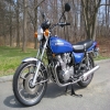
Just picked this baby up. I haven't owned a Kawasaki before got a steal on it. It's currently not running, but it cranks. Is there any place I should start as far as just general problems that these all have? Maybe there is a sticky for nubies but I didn't really see one. I'm an ASE certified mechanic and I have an A&P liscense but have never worked on motorcycles. I thought it would be a great project. This bike is clean, It wouldn't take a whole lot for it to look like new. It was a 1 owner(he got it for HS graduation in 1981). I super excited about this thing. Any help is greatly appreciated!
Torrey
By things to check, I don't mean compression, spark, fuel. I mean quirky things specific to this model(if there is any), that could cause you headaches if you didn't know about them. Thanks again!
Torrey
By things to check, I don't mean compression, spark, fuel. I mean quirky things specific to this model(if there is any), that could cause you headaches if you didn't know about them. Thanks again!
Last edit: 05 Mar 2011 15:58 by TorreyJ.
Please Log in or Create an account to join the conversation.
- TorreyJ
-
Topic Author
- Offline
- User
- Posts: 72
- Thanks: 1
Re: NEW BIKE, first KZ 1981 csr 650 19000 original mi
05 Mar 2011 16:04 - 05 Mar 2011 16:05
here it is. stock as stock

Attachments:
Last edit: 05 Mar 2011 16:05 by TorreyJ.
Please Log in or Create an account to join the conversation.
- MFolks
-

- Offline
- User
- Posts: 6650
- Thanks: 540
Re: NEW BIKE, first KZ 1981 csr 650 19000 original mi
05 Mar 2011 17:13
A good website for these 650's is
www.kz650.info/
I found these carb cleaning procedures sometime ago:
Carb Cleaning 101(Part 1)
By M. Shively
The elements of internal combustion engines are: correct fuel/air ratio, spark at right time, and adequate cylinder compression.
There are many passageways and openings to check and clean. All are important in function and when obstructed or not working properly, have subtle to radical effects on engine performance. Vacuum leaks and carburetor synchronization also effect performance and should be inspected and adjusted following the below procedures.
Warning: Remove all rubber parts before you begin. These parts usually include vacuum diaphragms, needle valves, o'rings, hoses, and other parts. Spray cleaners will damage these parts. Do not disassemble individual carbs from the carb bracket.
Air & Fuel Passageways: Trace and learn individual fuel and air circuits from beginning to end. Machines can only drill straight through the cast passageways. To change direction, another angled passageway must be drilled. The union is plugged with a brass or bronze bead. Inspect and clean each passageway with spray cleaner, brushes/pipe cleaners/etc, and compressed air. Remove any discoloration and debris. Look for spray cleaner to exit from one or more passageways.
Jet Cleaning: Inspect jets by holding to light and look through them. You should see an unobstructed round hole. Clean the jets with one or more of the following: jet cleaning wires, soak solutions, carb spray cleaners and compressed air. Re-inspect jets after cleaning and install when clear of obstructions. Some main jets have paper-like gaskets. Most have metal spacers between the jet and the emulsion tube. Some screw directly into a brass emulsion tube which is machined for a 7mm wrench at its float chamber exposed base.
Inlet Fuel Valve: Inspect the needle valve & spring. Press down the tiny metal rod that protrudes from the butt or float end of the needle valve. The spring should move freely and return the rod to its location. Check the needle valve's seat area for a groove or other wear. It should appear highly polished. Some needle valve seats are rubber and wear may not be visible. Inspect the needle valve jet seat. You can clean the jet seat with Q-tips and semi-chrome polish if necessary.
Carb Body Castings: Blow air through the atmospheric vent holes located on the dome of each float bowl chamber. Air should exit via hoses or brass nipples. Inspect the emulsion tubes and passageways (cast towers that jets thread into) for discoloration and debris. Clean interior emulsion towers with a soft bristle gun cleaning brush. Clean each Venturi (main carb bore).
Needle Jets & Jet Needles: Clean the needle jets, jet needles, and passageway or tower that needle jet screws into. Clean the emulsion tube (pipe between needle jet and main jet) (Main Jet may screw into emulsion tube). Jet needles are part of the throttle slides. See below…
Throttle Slides: There are several types of throttle slides: Mechanical linkage, vacuum, diaphragm, and cable. Disassembling the jet needle from the slide is not always required for cleaning. If you have vacuum piston type throttle slides (large diameter solid metal slide), avoid cleaning the lubrication from sides and caps. If piston type check cap vents and passageways with air. Clean if necessary and re-lube. If you have rubber vacuum throttle diaphragms, inspect for dry-rot, defects, and tears by gently stretching rubber away from center. Do this until all areas around diaphragm have been inspected. Replace any defective part as described above. Clean carb body areas around diaphragm including air passageways and air jets. Diaphragms have a locator loop or tab fabricated into their sealing edge. Observe this locator upon reassembly. Avoid pinching the diaphragm when reinstalling caps.
Fuel Screws: Fuel screws have sharp tapered ends. Carefully turn one fuel screw in while counting the turns until it seats lightly. Warning: These screws are very easily damaged if over tightened into their seats. Record amount of "turns-in" and remove the fuel screw, spring, washer, and o'ring. The fuel screw is part of the enrichment (choke) circuit...clean passageways as described above. When carbs are assembled, spray low PSI compressed air into diaphragm air vents located at intake side of carbs. Throttle slides should rise, then fall when air is removed. Lightly lube external moving linkages. Reinstall carbs and follow through with carburetor synchronization.
Throttle Cables: Lubricate cables periodically. If cables are disconnected from carbs or removed for replacement, etc . . . remember cable routing and ensure proper reinstallation routing. Avoid bread-tying, sharp bends, and pinching cables. Adjust cables so throttle grip has about 5mm of play or throttle slides or butterfly valves may not open completely (full throttle)(wide full open).
Float Bowls: Inspect float bowls for sediment, gum or varnish, crystallization, and defects. Clean all pipes, tubes, passageways, and embedded jets with cleaners and compressed air. Remove and clean the drain screw and area. Inspect bowl gasket and replace if necessary. Clean and inspect overflow pipes and tubes, look for vertical cracks.
Floats: There are several types of float materials: plastic, brass, black composite, tin, and others. Handle floats carefully. Avoid bending, twisting, denting, or other means of mishandling. Most floats are adjustable by bending a small metal tab near the float axle end. Do not change the float adjuster tab unless tuning fuel service levels. Clean metal floats by soaking or by spraying cleaner and wiping clean. Other material type floats may require replacement if cleaning is necessary. Inspect the needle valve (float valve) and seat. Check needle valve's spring loaded pin. It should depress and return smoothly and without resistance. Check the needle valve's tip for a worn groove. Replace needle valve and seat if either symptom exists. These parts wear together and must be replaced as a set.
Synchronization: This is a fine adjustment performed usually and preferably with the carbs installed and the engine running. The unusual part is performed with gauged wire with the carbs on the work bench. Carburetor synchronizing balances Venturi vacuum at the exhaust side of each carburetor, resulting with smooth idling and optimized performance at all throttle openings. Synchronization is checked using a set of gauges which are either air vacuum type or liquid mercury type. The gauges are connected to vacuum ports on the intake manifolds via nipple tubes or if sealed with screws, sync gauge adapters will be needed. With the engine running at temperature, and with a fan or means of forced convection aimed onto the engine, the carbs fuel screws and idle are adjusted, then the synchronization is adjusted via adjustment screws on the carbs. A reserve fuel tank is recommended for convenience of accessing carbs during this procedure. See gauge instructions and repair manuals for detailed use of synchronization gauges.
Notes: While carbs are apart, record the jet sizes. Look for a very small number imprinted on the body of the jets. Verify that numbers are the same for all jets on models with in-line cylinders. A few transverse-4 models and V-engines, the inner and outer carbs use some different size jets and it's important to not mix them up. If you have dial or veneer calipers, measure and record float heights. Perform measurements with floats just touching needle valves, though not depressing the needle valve rods. Replace fuel and vacuum hoses. Be sure to use fuel rated hose for fuel. Install or replace in-line fuel filters. It's a good time to remove and clean interior petcock fuel filters. Inspect carb manifolds for dry-rotting, inspect all clamps and air ducts. Inspect, clean, lube, and/or replace air filter(s).
1982 GPZ1100 B2
General Dynamics/Convair 1983-1993
GLCM BGM-109 Tomahawk, AGM-129A Advanced Cruise Missile (ACM)
General Dynamics/Convair 1983-1993
GLCM BGM-109 Tomahawk, AGM-129A Advanced Cruise Missile (ACM)
Please Log in or Create an account to join the conversation.
- MFolks
-
- Offline
- User
- Posts: 6650
- Thanks: 540
Re: NEW BIKE, first KZ 1981 csr 650 19000 original mi
05 Mar 2011 17:15
Part 2:
Carb Cleaning 102
Written by MShively
Most carburetor problems seem to come after the motorcycle was stored or not started for a while. If it won't start or only runs with the choke lever pulled out, you have one or more jets obstructed by gummed or varnished fuel. Notice the enrichening lever...most of the motorcycle carbs have enrichening passages inside the carburetor that WHEN THE THROTTLE IS CLOSED, provide the rich air/fuel mixture to start the engine. If you open the throttle any at all it cuts this enrichening out of the system. So if you are having trouble starting and everything looks ok, see if closing the throttle helps. This does not apply to carbs with a butterfly choke.
To access the jets you will have to take the carbs off the engine. A service manual will be very helpful here for specifications, images of the carburetor, and procedures. Take a float bowl off and remove the jets. Sometimes removing the jets can be difficult because the fuel has gummed or varnished over the parts. If so, clear as much of the gum out as possible. Use carb cleaner and compressed air to aid removal. Before soaking carbs in a dip tank or powerful cleaner, look for rubber seals, O'rings, and other parts that may be damaged by the cleaners. Remove any rubber parts prior to cleaning. Look closely, sometimes these parts are hard to see. If they are there and you can't get them, you will have to clean the carb body carefully by hand and not soak it.
Before you remove the fuel/air screw, gently turn it in until it seats. Count and record the number of "turns in." After cleaning and when you replace it, set it at this setting. Most carbs have a rubber o-ring and steel washer under the fuel/air screw spring. Look for them and remove them with a piece of wire or suitable fabricated tool BEFORE you spray carb cleaner in there. The fuel/air screw may be covered by a tamper cap or plug. You will have to remove this plug to access it. Upon reassembly and after cleaning, a base setting for the fuel/air screws of 1.25 turns out is good to start if you don't have the factory specs or forgot to record the turns out earlier. When the engine is warm, turn the screw in until the engine stumbles, then out until it stumbles, and leave it at half way in between. Adjust the idle with the throttle stop screw as needed.
You will need to remove the main jet and the needle jet. The main jet is usually larger and screwed onto the lower end of the needle jet, locking it into the emulsion tower and carb body. Remove the main jet and tap out the needle jet. Do this very carefully. It is soft brass and may break or damage very easily. Sometimes the needle jet will have an O-ring. Remove the O-ring and soak both main jet and needle jet in carb cleaner. Upon reassembly, there may be a locator pin in the emulsion tower/carb body that fits in a grove on the needle jet. Make sure they align properly.
You will need to remove the pilot jet. Pilot jets may be located similar as the main jet, covered by a rubber plug, deep inside an emulsion tower, or other. Be careful not to strip or break the small pilot jet when you try to remove it. It may be necessary to grind the end of a small screwdriver to fit the jet just right. Even after soaking, the jet may still be plugged. Use a small "E" guitar string and push it through the jet. (A wire strand out of a wire brush may work. The wire brush should measure about .013" in diameter.) The smallest jet drill you can get is #80, which has a diameter of .0135". You can use the wire and not enlarge the hole, at least not by much. Yes, some manuals say not to insert any wire jet cleaning tools into the jets. However, Honda and other manufacturers produce them as special tools for the dealer technicians.
Use compressed air with spray cleaner and the wire to clean jets. Spray carb cleaner into the carb passages, and then follow with compressed air. Watch for cleaner to exit from other passage ways and openings, and ensure that those small idle passages are clear. The smallest tubes, passageways, and openings are critical to the operation of the carburetor. EVERY PINHOLE IS IMPORTANT. Make certain that your see and hear air and cleaner pass freely through every opening. Wear goggles and don't get so close that you get carb spray in your eyes.
Sometimes the pins or rods that hold the floats can be gummed. Spray a bit of carb cleaner and let it set awhile. Repeat and try to gently move the float. Eventually, the pin will loosen enough so that you can drive out the pin with a very small punch. If necessary, tap on the punch very gently with the handle of a small screwdriver or similar tool. Penetrating oil also works good to free up gummed float pins and stuck throttle slides. If the slides have a rubber diaphragm on them, spray carb cleaner on a rag and wipe the slide clean. Do not get carb cleaner on the rubber diaphragms. It will ruin them. While you have the Diaphragm out, inspect it for holes. If you have an engine that has good compression and starts well, but just has no power and revs up ever so slowly, check that rubber diaphragm. It may have a hole or tear. The throttle slide will not rise if it is damaged.
When you put the float valve or needle valve back in place, put a drop of light oil on it so it will move freely in its seat and not stick before the gas first starts to fill the bowl.
Don't clean the outside of constant velocity (CV) carbs with spray carb cleaner unless you are sure they are not the rubber diaphragm type. Carb cleaner will ruin the rubber. There is a piston type of CV carburetor, but it's still not a good idea to use the spray because of rubber float bowl gaskets (O'rings).
If you turn on the fuel petcock and gas pours out the overflow tubes, tap lightly on the carb body with a suitable tool. That will vibrate the float valves loose. Same thing if there is dirt holding the valves open. If it doesn't work you need a new float valve & seat. The tips of the float valves can be steel or rubber. Tips with a groove worn in them should be replaced. The float pin springs often become gummed by fuel and cause the pins to stick. Test with your finger. They should be free moving - no resistance. Replace all if you feel any sticking. If they first stuck, but you worked them free, try and use them. They may fail when gasoline gets into the spring again.
Floats control the fuel level in the float bowls. Adjustable tangs on the floats rest on the float valve pins. When level is low, the float lowers and the valve follows. More fuel enters the bowl. Similarly, shutting fuel flow off when it replenishes supply. If the tang is metal, you can adjust the float level by bending the tang up or down. If it is plastic, it is non-adjustable. Float levels are different for each bike and are found in the bikes shop manual. If you don't have the float setting and can't find it anywhere, set it so the fuel level is a bit below the top of the float bowl. Make sure no gas comes out of the float overflow tubes or hoses. The float overflow tube is at the bottom or side of each float bowl. There are many styles of floats: copper, brass, bronze, plastic, urethane, tin, cork, and maybe other materials. Brass and plastic are the most common.
If the rubber ducts that connect the carb and air cleaner housing are hard and dry-rotted, you should replace them. Replace rubber intake manifolds if necessary, too.
On the side of some carbs is another diaphragm that temporarily closes the pilot or slow speed jet air passage when the throttle is closed. This richens the fuel mixture to reduce backfiring when coming to a stop. Check the diaphragm for holes and tears.
At the bottom of some carbs is an accelerator pump to pump extra fuel when the throttle is opened. The pump is attached or connected to one float bowl. Check the pump's diaphragm for holes or tears. A rubber coating called "Plasti-Dip" has been used to fix diaphragms. I have never used it but I hear it works. Get it from NAPA part #765-2527.
Adjustments that you can make from outside the carburetor:
1) Synchronizer screws balance the carburetors for smooth performance and idling. 2) Idle screw (throttle stop screw) adjusts the speed of the idle. 3) The idle fuel/air screw adjusts the idle mixture. This is only at idle and does not effect anything above idle. Another method to adjust it: turn the fuel/air screw in and out until you get the highest idle speed. Then lower the idle speed with the idle screw and do it again until you get the best idle. The air screw can be located in a variety of places on the carb. If you have a 1980 or newer machine, it may have a cover over it to keep you from messing with it. You will have to drill it and then pry it out using the hole you made. It may be illegal for you to do this, depending on where you live.
If you can't get it to idle, or rather the idle stays real high then drops off and dies, check for an air leak. Spray starting fluid, WD40, brake cleaner, carb cleaner, etc... on the manifold, carbs, air box, vacuum hoses, and petcock to see if the revs change. If they do, you have a leak. If your valve clearances are too tight, it will also effect the idle.
You can make your air/fuel mixture a bit richer or leaner by moving the carburetor needle clip up or down. Move the clip down a notch to raise the needle, to richen the mixture. Move the clip up to lower the needle, to lean out the mixture. The needle is located in the throttle slide.
1982 GPZ1100 B2
General Dynamics/Convair 1983-1993
GLCM BGM-109 Tomahawk, AGM-129A Advanced Cruise Missile (ACM)
General Dynamics/Convair 1983-1993
GLCM BGM-109 Tomahawk, AGM-129A Advanced Cruise Missile (ACM)
Please Log in or Create an account to join the conversation.
- MFolks
-
- Offline
- User
- Posts: 6650
- Thanks: 540
Re: NEW BIKE, first KZ 1981 csr 650 19000 original mi
05 Mar 2011 17:30
The new bike, ignition points, or electronic ignition? Too find out, remove a CD sized cover on the right side of the engine.
My advise would be to replace the ignition coils as even when new, the coils were marginal, put some years on them with heat and vibration added and it's now time to replace them.
I wrote this to inspect the pickup(pulsing coils) on the bigger 4's, but the ohm readings should be the same:
Ohm Checking Pickup(Pulsing) Coils
The pickup coils on the Kawasaki’s with the factory supplied electronic ignition can sometimes fail or become intermittent due to heat and vibration.
1.Trace back from where the pick up coils are mounted,(under a right side CD sized cover) locate and disconnect a small 4 pin connector. Using a multi-meter set on OHMS and range of 2K, check between the BLUE and BLACK wires(#1 and #4 sparkplug wires) for between 360- 540 OHMS.
2.For #2 and #3 sparkplugs the wire colors will be YELLOW and RED, again 360-540 OHMS.
3.If the pickup coils are suspect of failing due to heat, they can be stressed using a hair dryer without the need of the engine running.
4.A replacement set of pickup coils might be obtained from a dealer who serviced the police Kawasaki’s.
5. If replacement pickup coils are not available, your next choice would be to order a Dyna “S†electronic ignition system from www.z1enterprises.com It replaces the IC igniter with a smaller module located where the mechanical ignition advancer was mounted.
6. Checking with Kawasaki.com website has determined that the Pick up(pulsing) coils are available . The pulsing coil # is 59026-1133 and replaces the older # 1002, 1012 which were used from the MKII motors until the 2005 P24.
7.Check the small 4 pin connector that the pickup coils connect to for corrosion/loose pins too.
And:
Ignition Coil Primary And Secondary Wiring
Ignition coils on the 80’s Kz1000,Kz1100’s and Gpz1100’s are wired the same, that is as you sit on the bike, the LEFT ignition coil primary(small wires) are two wires, RED and BLACK. The secondary (or sparkplug wires) go to #1 and #4 sparkplugs(your primary wiring may be different).
The cylinders are numbered left to right as you sit on the seat; #1,#2,#3, and #4.
For the RIGHT ignition coil, the primary wires, again are two wires, RED and GREEN, with the secondary going to #2 and #3.
The RED wire gets it’s voltage from the run/stop switch on the right handlebar switch pod.
The BLACK and GREEN wires connect to the IC Igniter(if the bike has the Kawasaki supplied electronic ignition) it actually gives the coils their grounds to fire the sparkplugs.
Primary(small wires) side of the coils will read between 1.8 to 3.0 ohms.
Secondary(sparkplug wire ports)side of the coil will read between 10.4K to 15.6K ohms. These ports are wired together, so it makes no difference which is used, as long as the correct coil to sparkplug configuration is followed.
The sparkplug caps should read 5K OHMS, any higher, or a reading of infinity means new caps should be ordered.
To stress the ignition coils, take a hair dryer, heat the coils and see if the ohm readings change from cold to hot . If they do, it’s time to buy new coils.
Keep in mind, the wiring is reversed for the 550’s 650‘s and 750‘s, that is the RIGHT coil primary will be two wires, RED and BLACK with the secondary(sparkplugs) going to #1 and #4.
The LEFT coils primary wiring would be again two wires, RED and GREEN, with the secondary(sparkplugs) going to #2 and #3.
These engines have what is known as a “Wasted Spark†that is, a sparkplug will fire during an exhaust stroke. It does no damage and many other motorcycle engines have this design.
1982 GPZ1100 B2
General Dynamics/Convair 1983-1993
GLCM BGM-109 Tomahawk, AGM-129A Advanced Cruise Missile (ACM)
General Dynamics/Convair 1983-1993
GLCM BGM-109 Tomahawk, AGM-129A Advanced Cruise Missile (ACM)
Please Log in or Create an account to join the conversation.
- TorreyJ
-
Topic Author
- Offline
- User
- Posts: 72
- Thanks: 1
Re: NEW BIKE, first KZ 1981 csr 650 19000 original mi
05 Mar 2011 17:51
um...don't know how to say thank you for that! you rock! I paid $400 for the bike. its so "stock pretty," if that makes sense. I appreciate this!
Please Log in or Create an account to join the conversation.
- MFolks
-
- Offline
- User
- Posts: 6650
- Thanks: 540
Re: NEW BIKE, first KZ 1981 csr 650 19000 original mi
05 Mar 2011 19:27
No problem! I have a lot of information on my computer system that I just cut and paste for motorcycle problems.
1982 GPZ1100 B2
General Dynamics/Convair 1983-1993
GLCM BGM-109 Tomahawk, AGM-129A Advanced Cruise Missile (ACM)
General Dynamics/Convair 1983-1993
GLCM BGM-109 Tomahawk, AGM-129A Advanced Cruise Missile (ACM)
Please Log in or Create an account to join the conversation.
- TorreyJ
-
Topic Author
- Offline
- User
- Posts: 72
- Thanks: 1
Re: NEW BIKE, first KZ 1981 csr 650 19000 original mi
05 Mar 2011 20:14
such a great looking bike. I'm thinking swap the bars for a strait shot, get rid of the passenger headrest. I hate the seat. any suggestions? I don't have any doubt on gettning it runnning. but. can can you swap some sort of full plastics to this bike. I thought i saw it somewhere. Its so beautifully stock i almost just want to restore it.
Please Log in or Create an account to join the conversation.
- 650ed
-
- Offline
- User
- Posts: 15343
- Thanks: 2829
Re: NEW BIKE, first KZ 1981 csr 650 19000 original mi
05 Mar 2011 20:24 - 05 Mar 2011 20:28
TorreyJ wrote:
Take a look at this one; I think it looks good; yours is already pretty close to it if you like its looks:
81 CSR
such a great looking bike. I'm thinking swap the bars for a strait shot, get rid of the passenger headrest. I hate the seat. any suggestions? I don't have any doubt on gettning it runnning. but. can can you swap some sort of full plastics to this bike. I thought i saw it somewhere. Its so beautifully stock i almost just want to restore it.
Take a look at this one; I think it looks good; yours is already pretty close to it if you like its looks:
81 CSR
1977 KZ650-C1 Original Owner - Stock (with additional invisible FIAMM horn)
Last edit: 05 Mar 2011 20:28 by 650ed.
Please Log in or Create an account to join the conversation.
- TorreyJ
-
Topic Author
- Offline
- User
- Posts: 72
- Thanks: 1
Re: NEW BIKE, first KZ 1981 csr 650 19000 original mi
05 Mar 2011 21:05
so it was $400 I think i stole it...
Please Log in or Create an account to join the conversation.
- martin_csr
-

- Offline
- User
- Posts: 8019
- Thanks: 1645
Last edit: 11 Feb 2013 13:13 by martin_csr.
Please Log in or Create an account to join the conversation.
- TorreyJ
-
Topic Author
- Offline
- User
- Posts: 72
- Thanks: 1
Re: NEW BIKE, first KZ 1981 csr 650 19000 original mi
05 Mar 2011 21:06
I WANT those wheels. Anybody want to trade for a pair of almost pristine spokes? 
Please Log in or Create an account to join the conversation.