
81 Kz750 ltd no spark
- Hbomb440
-
 Topic Author
- Offline
- User
-

Registered
- Posts: 32
- Thanks: 4
81 Kz750 ltd no spark
11 Jul 2021 16:22 - 11 Jul 2021 16:23
Ok guys back to for more help and information. This project I took on seems to a can of worms that doesn't ever seem to stop. Right now I have no spark and can't seem to figure out what the issue is and don't really have the money to just start throwing money blindly at parts. When I picked it up the bike ran at like 4 to 5k. Its been a little over a year and want to get this back to the owner. I have cleaned almost all the wire plugs on the bike even had to replace one. I have a multi meter and im pretty sure the coils are good unless im testing them wrong. An6 help would be greatly appreciated guys im really getting out of my wheelhouse of knowledge here. Its a 81 kz750 ltd H bike and here are a few fun bikes from it.
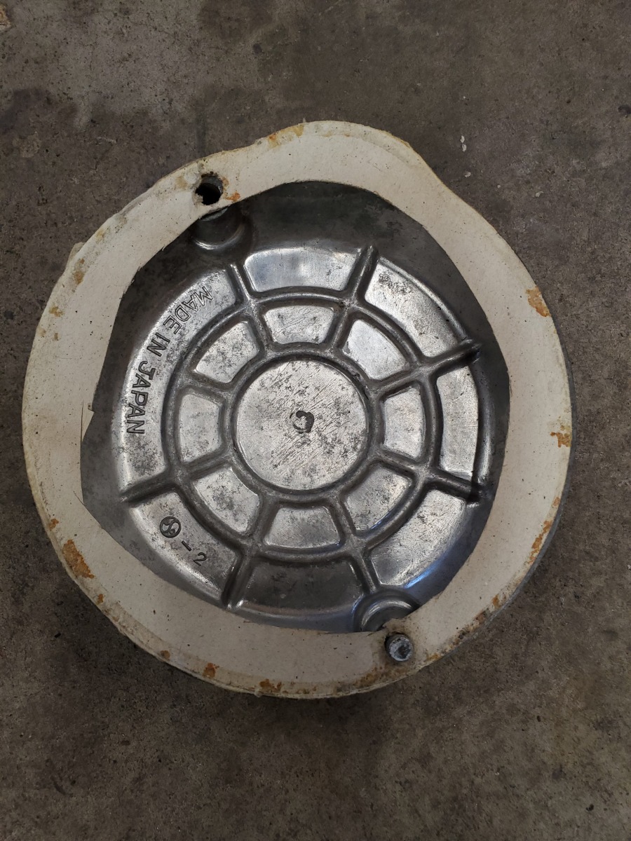
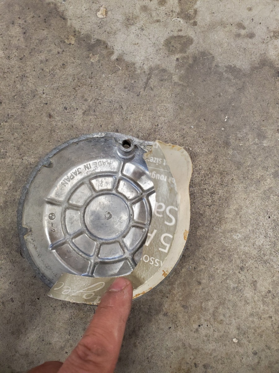
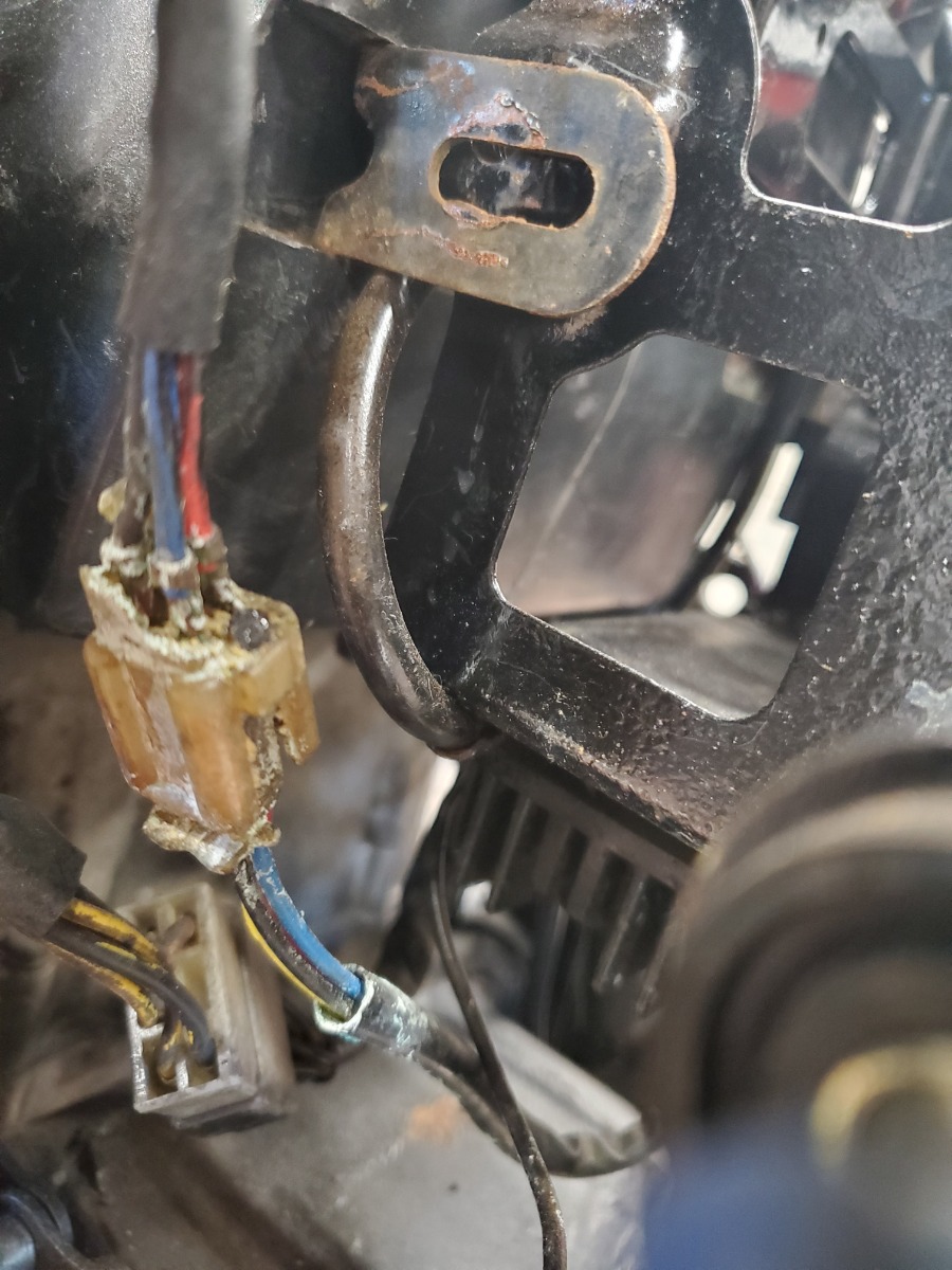
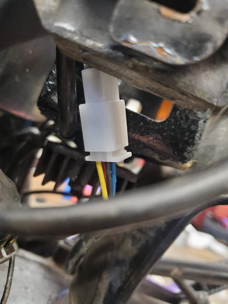
81 KZ750H
Last edit: 11 Jul 2021 16:23 by Hbomb440.
Please Log in or Create an account to join the conversation.
- F64
-

- Offline
- User
-
Registered
- 81-KZ440D2
- Posts: 1180
- Thanks: 430
Re: 81 Kz750 ltd no spark
11 Jul 2021 17:52 - 11 Jul 2021 17:59
meter on DC V
key on/Ignition on
black probe on negative battery post (post is the metal part of the battery)
red probe on positive battery post
note voltage
Move red probe to each of the ignition coil terminals
note voltages
Turn off bike
One of the terminals on each coil should be close to battery voltage.
The other terminal could either be close to 0 or battery voltage.
I just want to verify the coils are receiving battery voltage first.
81-KZ440-D2.
Louis Dudzik's GM HEI ignitor conversion installed 2015 s3.amazonaws.com/gpzweb/Ignition/GPZgmHEImod.html
Motogadget m-unit blue installed 2017.
LIC, NY
Louis Dudzik's GM HEI ignitor conversion installed 2015 s3.amazonaws.com/gpzweb/Ignition/GPZgmHEImod.html
Motogadget m-unit blue installed 2017.
LIC, NY
Last edit: 11 Jul 2021 17:59 by F64.
Please Log in or Create an account to join the conversation.
- Hbomb440
-
Topic Author
- Offline
- User
-
Registered
- Posts: 32
- Thanks: 4
Re: 81 Kz750 ltd no spark
12 Jul 2021 14:55
Thank you I ended up getting stuck at work today so wont get a chance to do anything today but after work tomorrow will do and update results.
81 KZ750H
Please Log in or Create an account to join the conversation.
- Hbomb440
-
Topic Author
- Offline
- User
-
Registered
- Posts: 32
- Thanks: 4
Re: 81 Kz750 ltd no spark
13 Jul 2021 19:43
Ok so got a chance to go and check it out and all four leads to coils read battery voltage or just under forgot to write them down if needed ill get a chance to do it again in a day or two. Voltage on battery started out at like 12.7 and when done was at 11.9. Could battery be bad? It cranks over with ease. Odd question nut popped into my head while in front of the coils could they not be getting a good ground?
81 KZ750H
Please Log in or Create an account to join the conversation.
- F64
-
- Offline
- User
-
Registered
- 81-KZ440D2
- Posts: 1180
- Thanks: 430
Re: 81 Kz750 ltd no spark
13 Jul 2021 19:55 - 13 Jul 2021 20:32
The ground to the coils is supplied by the igniter
And you are more likely to see the coil grounded than open.
Lou is going to have to jump in on this as I have a feeling there are a few things that must happen before the coils are grounded by the igniter.
We should check the leads going into the igniter as well.
Your battery has enough juice to fire the plugs.
Your coils are receiving voltage. They just aren't charging right now. If they were, you would see 0 volts on half of the coil terminals.
81-KZ440-D2.
Louis Dudzik's GM HEI ignitor conversion installed 2015 s3.amazonaws.com/gpzweb/Ignition/GPZgmHEImod.html
Motogadget m-unit blue installed 2017.
LIC, NY
Louis Dudzik's GM HEI ignitor conversion installed 2015 s3.amazonaws.com/gpzweb/Ignition/GPZgmHEImod.html
Motogadget m-unit blue installed 2017.
LIC, NY
Last edit: 13 Jul 2021 20:32 by F64.
Please Log in or Create an account to join the conversation.
- loudhvx
-

- Offline
- KZr Legend
-

Registered
- Posts: 10863
- Thanks: 1622
Re: 81 Kz750 ltd no spark
13 Jul 2021 22:44 - 13 Jul 2021 22:58
Like F64 said, the coils get grounded through the igniter.
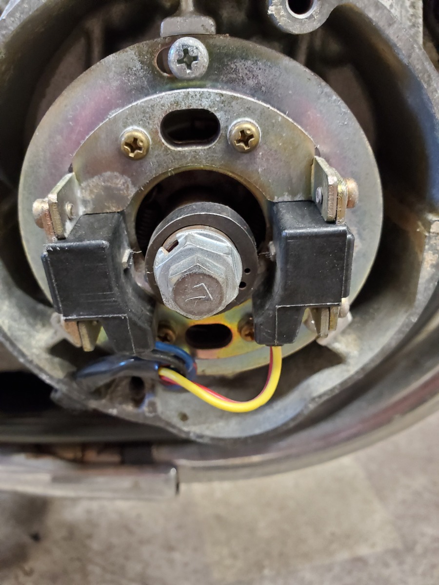
With the factory ignition, when the crankshaft is not turning you should see battery voltage on the four small wires on the coils, as you reported. Battery voltage goes to the coils through the yellow or red wire on the coils. When the crank turns, the green wire and the black wire will alternate getting ground from the igniter. This way the coils alternate charging and resting. When running, each coil spends about 1/3 time charging with the black or green wire grounded, and about 2/3 of the time resting. During startup, the charge time fraction will be much smaller, so the time the wires get grounded will be very brief pulses. In all situations, both coils should never be charging at the same time.
Side note regarding the Dyna S ignition: With the Dyna S, when the crankshaft is not turning, both coils are charging all the time (and getting hot). So the ground side of the coils are close to 0 volts (usually around 1 volt) most of the time. When the crankshaft turns, the coils will alternate resting briefly, where the green wire and black wire will briefly have near battery voltage on them. Each coil spends about 7/8 of the time charging, and about 1/8 of the time resting. I'm only mentioning this since there are plenty of people using Dyna S ignitions on Kz's.
When checking for spark, make sure there is a path for the plug wires to spark to a common piece of metal in order to prevent damage to the igniter or coils.
You can try to use a meter to measure the green or black wire to see if it does indeed pulse toward ground when the crank turns. But at startup speed, the pulses are very brief. Also there will be spikes of up to potentially 600 volts on those wires which may be bad for the meter. You can reduce the danger by making sure both plug wires are shorted to each other on each coil. That will prevent the high voltage spike.
If you want to bench test the system you can wire it up like this diagram. Then just tapping the pole on a pickup should create a spark on a coil.
1981 KZ550 D1 gpz.
Kz550 valve train warning.
Other links.
Kz550 valve train warning.
Other links.
Last edit: 13 Jul 2021 22:58 by loudhvx.
The following user(s) said Thank You: F64
Please Log in or Create an account to join the conversation.
- Hbomb440
-
Topic Author
- Offline
- User
-
Registered
- Posts: 32
- Thanks: 4
Re: 81 Kz750 ltd no spark
14 Jul 2021 13:05
Ok thank you guys dont know if i really want to take all that off the bike seems every time i take something off this bike come up with new problems. Wont be able to do anything today but hopefully tomorrow night. I really appreciate all the help guys this is out of my normal wheelhouse
81 KZ750H
Please Log in or Create an account to join the conversation.
- F64
-
- Offline
- User
-
Registered
- 81-KZ440D2
- Posts: 1180
- Thanks: 430
Re: 81 Kz750 ltd no spark
14 Jul 2021 14:41
Later tonight I will grab a schematic and see what we can test voltage-wise to the ignitors.
Probably can also test your ignition
pick ups as well.
Thanks Lou for talking about the ignitor.
Probably can also test your ignition
pick ups as well.
Thanks Lou for talking about the ignitor.
81-KZ440-D2.
Louis Dudzik's GM HEI ignitor conversion installed 2015 s3.amazonaws.com/gpzweb/Ignition/GPZgmHEImod.html
Motogadget m-unit blue installed 2017.
LIC, NY
Louis Dudzik's GM HEI ignitor conversion installed 2015 s3.amazonaws.com/gpzweb/Ignition/GPZgmHEImod.html
Motogadget m-unit blue installed 2017.
LIC, NY
The following user(s) said Thank You: loudhvx
Please Log in or Create an account to join the conversation.
- F64
-
- Offline
- User
-
Registered
- 81-KZ440D2
- Posts: 1180
- Thanks: 430
Re: 81 Kz750 ltd no spark
14 Jul 2021 19:02 - 14 Jul 2021 20:48
Ok,
Meter on DC V
Key on/ignition on
Black probe battery negative post
Red probe battery positive post
Note voltage
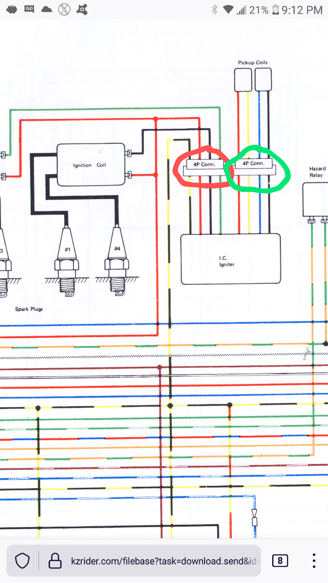
Note-back probe the ignitor connector from the ignitor side. This will rule out bad connector terminals. Also leave all connections connected. Voltage drop tests need the circuit complete)
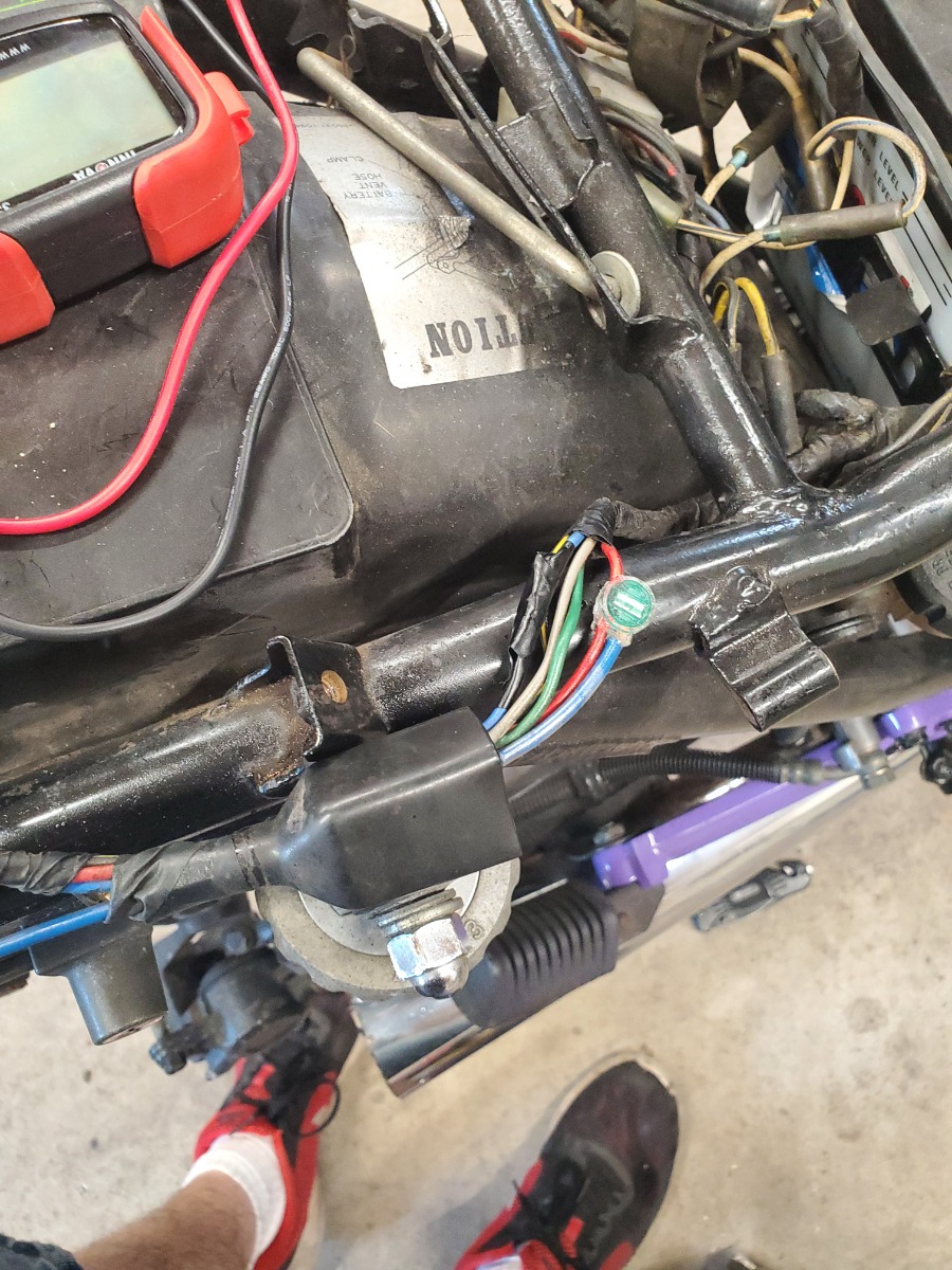
Move red probe to the black/yellow wire in red circle(connector for the ignition system ignitor. Possibly hiding under a side cover)
Note voltage
Should be 0 volts or very close. Any higher than 0.5V then you have a big voltage drop on your yellow/black wire which is a ground wire.
Move red probe to red wire. Should be close to battery voltage.
Move red probe to green wire in red circle. Crank starter.
Note if voltage fluctuates between 0 and battery voltage.
Move probe to black wire in red circle.
Crank starter.
Voltage should fluctuate between 0 and 12v.
The 0v should just be a blip. It will mostly be 12V. Same with the green wire above.
Green circle time.
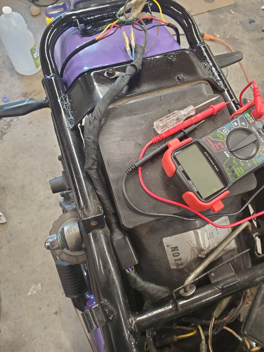
Meter on AC V
Red probe on red wire
Black probe on yellow wire.
Crank engine.
You should see an ac voltage of a couple of volts as the engine turns.
Green circle connector again
Red probe on blue wire
Black probe on black wire
Crank engine.
Note AC voltage.
Turn off bike
Schematic courtesy of angie(biker_gal_uk)
Meter on DC V
Key on/ignition on
Black probe battery negative post
Red probe battery positive post
Note voltage
Note-back probe the ignitor connector from the ignitor side. This will rule out bad connector terminals. Also leave all connections connected. Voltage drop tests need the circuit complete)
Move red probe to the black/yellow wire in red circle(connector for the ignition system ignitor. Possibly hiding under a side cover)
Note voltage
Should be 0 volts or very close. Any higher than 0.5V then you have a big voltage drop on your yellow/black wire which is a ground wire.
Move red probe to red wire. Should be close to battery voltage.
Move red probe to green wire in red circle. Crank starter.
Note if voltage fluctuates between 0 and battery voltage.
Move probe to black wire in red circle.
Crank starter.
Voltage should fluctuate between 0 and 12v.
The 0v should just be a blip. It will mostly be 12V. Same with the green wire above.
Green circle time.
Meter on AC V
Red probe on red wire
Black probe on yellow wire.
Crank engine.
You should see an ac voltage of a couple of volts as the engine turns.
Green circle connector again
Red probe on blue wire
Black probe on black wire
Crank engine.
Note AC voltage.
Turn off bike
Schematic courtesy of angie(biker_gal_uk)
81-KZ440-D2.
Louis Dudzik's GM HEI ignitor conversion installed 2015 s3.amazonaws.com/gpzweb/Ignition/GPZgmHEImod.html
Motogadget m-unit blue installed 2017.
LIC, NY
Louis Dudzik's GM HEI ignitor conversion installed 2015 s3.amazonaws.com/gpzweb/Ignition/GPZgmHEImod.html
Motogadget m-unit blue installed 2017.
LIC, NY
Last edit: 14 Jul 2021 20:48 by F64.
The following user(s) said Thank You: Hbomb440
Please Log in or Create an account to join the conversation.
- loudhvx
-
- Offline
- KZr Legend
-
Registered
- Posts: 10863
- Thanks: 1622
Re: 81 Kz750 ltd no spark
14 Jul 2021 19:49 - 14 Jul 2021 19:53
The green and black wires should mostly be at 12v. When cranking, you should see blips of 0v. I should have been more clear in my previous post. I'll delete this post if you edit yours, to avoid confusion.
1981 KZ550 D1 gpz.
Kz550 valve train warning.
Other links.
Kz550 valve train warning.
Other links.
Last edit: 14 Jul 2021 19:53 by loudhvx.
Please Log in or Create an account to join the conversation.
- F64
-
- Offline
- User
-
Registered
- 81-KZ440D2
- Posts: 1180
- Thanks: 430
Re: 81 Kz750 ltd no spark
14 Jul 2021 20:50 - 14 Jul 2021 21:37
Thanks Lou!
Leave your post up.
I edited my post to match your info.
I didn't realize the ignitor limits the charge time on the coils to that extent. It's good to know.
So could you use a coil with a lower resistance primary without fear of overheating the coil?
Leave your post up.
I edited my post to match your info.
I didn't realize the ignitor limits the charge time on the coils to that extent. It's good to know.
So could you use a coil with a lower resistance primary without fear of overheating the coil?
81-KZ440-D2.
Louis Dudzik's GM HEI ignitor conversion installed 2015 s3.amazonaws.com/gpzweb/Ignition/GPZgmHEImod.html
Motogadget m-unit blue installed 2017.
LIC, NY
Louis Dudzik's GM HEI ignitor conversion installed 2015 s3.amazonaws.com/gpzweb/Ignition/GPZgmHEImod.html
Motogadget m-unit blue installed 2017.
LIC, NY
Last edit: 14 Jul 2021 21:37 by F64.
Please Log in or Create an account to join the conversation.
- loudhvx
-
- Offline
- KZr Legend
-
Registered
- Posts: 10863
- Thanks: 1622
Re: 81 Kz750 ltd no spark
14 Jul 2021 22:40 - 14 Jul 2021 23:06
That very short pulse is just during cranking. The RPM is so low that the pickup signal is very small. Being small, it can only cross the required threshold briefly. This is nice in that it doesn't waste any battery power during the critical time of starting.
Once the bike is idling, the crank is spinning fast enough such that the shape of the reluctor rotor starts to become the limiting factor for charge time. The rotor is designed with about 120 degrees of increasing radius and 240 degrees of decreasing radius. When the crank is turning fast enough, the charge time, aka dwell time, is that time during which the increasing radius is passing by the pickup. When the crank is turning slower, the dwell time will reduce a bit. In practice, the dwell at idle is closer to about 100 degrees. As the RPMs increase, the dwell starts to approach the 120 degree limit. This is usually a few hundred RPM above idle. It's a clever way of getting a changing dwell angle without having to use any circuitry to accomplish it. At idle you don't need a lot of charge time so reducing it saves battery power. It's all done by the clever shape of the reluctor rotor.
As a side note, another clever aspect of the shape is that it is asymmetrical. This ensures the two ignition signals don't cross zero at the same time. This eliminates crosstalk between circuits, natively. (Too bad Honda didn't copy that design.) Whoever designed that ignition did an incredible job of giving it sophisticated behavior while also being ridiculously simple.
The 120 degrees of dwell is very well matched to the stock 2.3 ohm (nominal) coils. I don't think it would be a good idea to go too much lower than 2 ohms. The coil may heat up more, but you also run the risk of exceeding the current capacity of the igniter.
Here is a link to a stationary look at the pickup signals produced by the reluctor.
KzRelucSignalApprox_copy.GIF (740×900) (gpzweb.s3-website-us-east-1.amazonaws.com)
This animation shows how the rotor position relates to the signals. The right edge of the signal portion of the image is coordinated to the position of the rotor.
1981 KZ550 D1 gpz.
Kz550 valve train warning.
Other links.
Kz550 valve train warning.
Other links.
Last edit: 14 Jul 2021 23:06 by loudhvx.
The following user(s) said Thank You: TexasKZ, F64
Please Log in or Create an account to join the conversation.
Moderators: Street Fighter LTD