
KZ400 harness wiring help
- FJR1
-
 Topic Author
- Offline
- User
-

Registered
- Posts: 20
- Thanks: 0
KZ400 harness wiring help
21 Apr 2019 13:49 - 21 Apr 2019 13:50
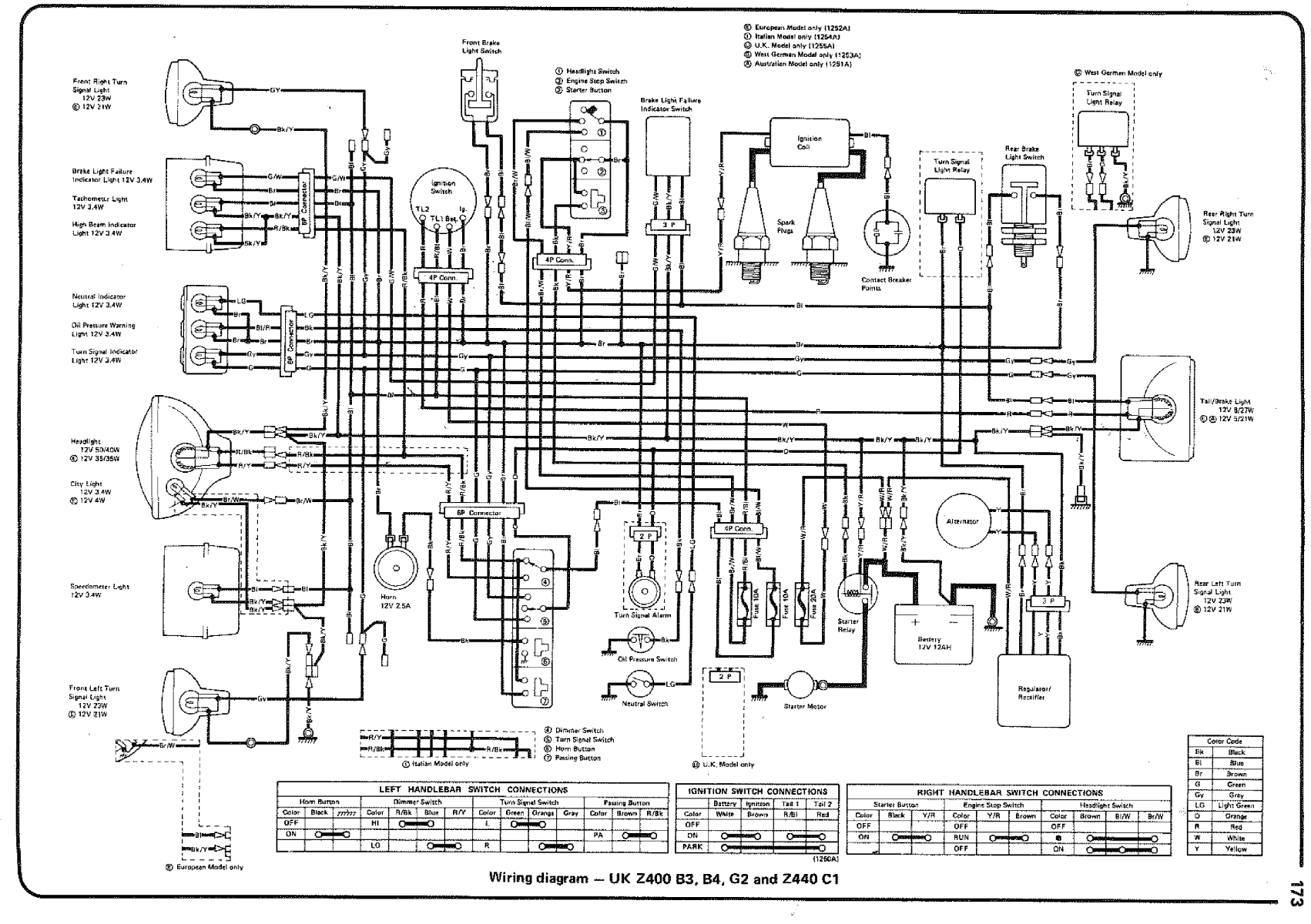
Hello guys. While it is Easter, I am working on sorting out the new harness for my KZ400 (G2 1981) cafe racer project. It is the first time that I am doing an harness I could use some advice and help.
My goal would be to make a more minimalist circuit.
Bellow is the original circuit versus a version of mine. I am a beginner so, there would be some mistakes.
Please, I would like a validation for the circuit and advice on how I can make it simpler.
I want to use the kick starter only, which I believe is available on the bike ( the pedal is there).
I have removed several components from the original diagram such as:
Brake light failure switch
Right and left turn signal indicator bulbs (tell-tale)
The break light failure indicator light (tell-tale)
Tachometer Light
High beam indicator (tell-tale)
Speedometer Light
Turn signal alarm
Starter button
Passing button
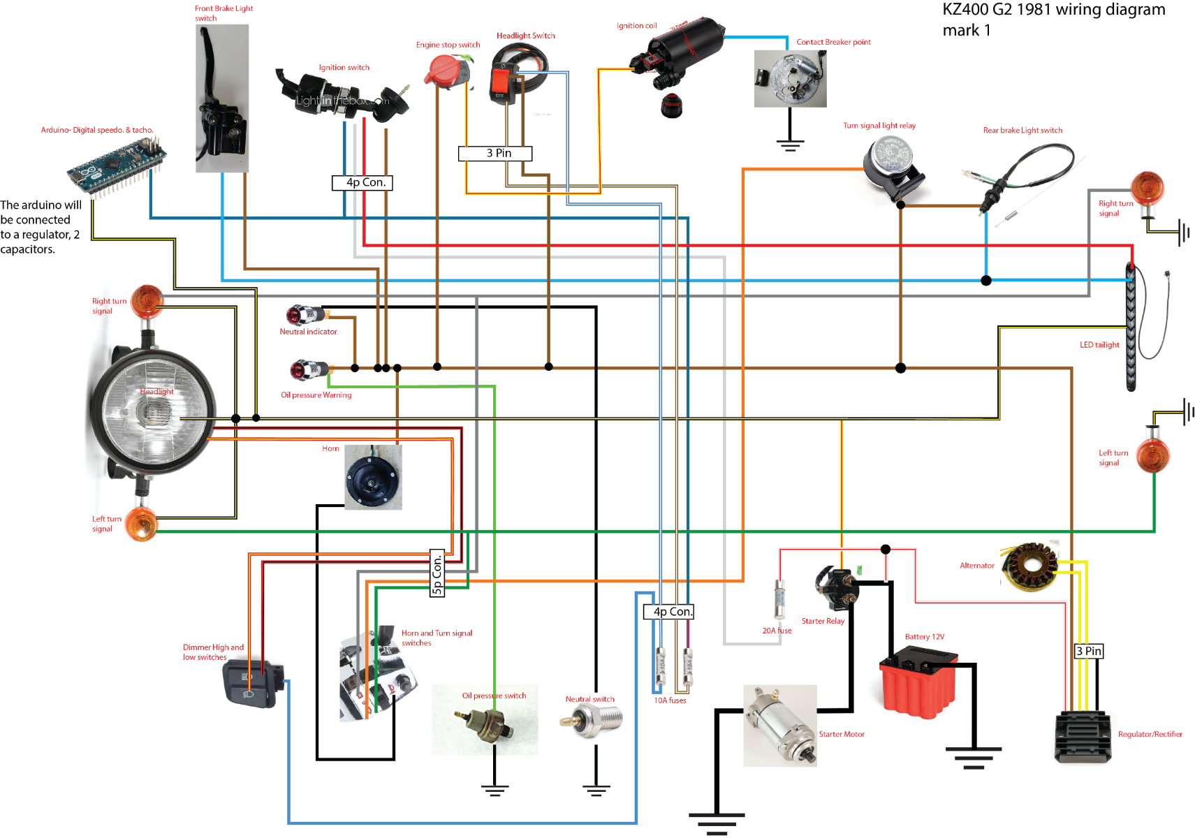
I have added:
An voltage regulator before the arduino nano
On the arduino an OLED screen will be connected to
show the speed which is measure with reed switch and magnet.
For the Tachometer I need to do more research.
Thank you in advance for your time, I greatly appreciate.
Note: I have not added the end connectors in my diagram between the main harness and the electronics, such as the headlight etc. if that makes sense.
My goal would be to make a more minimalist circuit.
Bellow is the original circuit versus a version of mine. I am a beginner so, there would be some mistakes.
Please, I would like a validation for the circuit and advice on how I can make it simpler.
I want to use the kick starter only, which I believe is available on the bike ( the pedal is there).
I have removed several components from the original diagram such as:
Brake light failure switch
Right and left turn signal indicator bulbs (tell-tale)
The break light failure indicator light (tell-tale)
Tachometer Light
High beam indicator (tell-tale)
Speedometer Light
Turn signal alarm
Starter button
Passing button
I have added:
An voltage regulator before the arduino nano
On the arduino an OLED screen will be connected to
show the speed which is measure with reed switch and magnet.
For the Tachometer I need to do more research.
Thank you in advance for your time, I greatly appreciate.
Note: I have not added the end connectors in my diagram between the main harness and the electronics, such as the headlight etc. if that makes sense.
Attachments:
Last edit: 21 Apr 2019 13:50 by FJR1.
Please Log in or Create an account to join the conversation.
- martin_csr
-

- Offline
- User
-
Registered
- Posts: 8018
- Thanks: 1645
Re: KZ400 harness wiring help
21 Apr 2019 16:50 - 22 Apr 2019 07:16
Simplified wiring diagrams. KZR topic by loudhvx.
bare bones for mattylight.
see pages 11-21.
Pg 19 has one for the 76 KZ400S & there are a couple for the 440. not sure if your bike is a Twin or 4-cyl. ???
note: some of the diagrams are no longer there >> pg 1-10. But from pg 11-on many are still available.
....
Pg 19 has one for the 76 KZ400S & there are a couple for the 440. not sure if your bike is a Twin or 4-cyl. ???
note: some of the diagrams are no longer there >> pg 1-10. But from pg 11-on many are still available.
....
Last edit: 22 Apr 2019 07:16 by martin_csr.
The following user(s) said Thank You: FJR1
Please Log in or Create an account to join the conversation.
- loudhvx
-

- Offline
- KZr Legend
-

Registered
- Posts: 10864
- Thanks: 1619
Re: KZ400 harness wiring help
21 Apr 2019 17:37 - 21 Apr 2019 17:56
There are a couple minor problems with the color diagram.
First, you don't actually show that there is a ground connection for the headlight, Arduino etc. That is, they have ground wires, but none of them are shown getting to an actual ground point like the battery's negative terminal or the frame.
Second, the headlight switch is puzzling. If wired like the original wiring of the bike with the headlight/gauge on/on/off options, it looks like the Arduino will turn off when the light switch is turned off. If that is the tach, wouldn't you want it to work whenever the bike is running? If so, the Arduino should be fed by the brown wire.
Also, the horn ground is not shown, but it will probably ground to the frame.
If you expect that the diagram might be read by other people who may not have access to the black/white diagram, you may want to include the switching logic charts as they are shown on the B/W diagram. That would make it easier to understand.
I don't think a reed switch will be fast enough for a speedometer. The magnet could go by so fast that the reed contacts don't have enough time to make contact. A hall-effect sensor is what you want. It's essentially and very low-power electronic version of a reed switch. But there are many kinds, so you will want to research it.
The shunting regulation of the charging system will not be nice to the Arduino, neither will the high-tension of the ignition system. You will want to build some test devices to make sure your power and isolation is adequate for the Arduino.
1981 KZ550 D1 gpz.
Kz550 valve train warning.
Other links.
Kz550 valve train warning.
Other links.
Last edit: 21 Apr 2019 17:56 by loudhvx.
The following user(s) said Thank You: FJR1
Please Log in or Create an account to join the conversation.
- FJR1
-
Topic Author
- Offline
- User
-
Registered
- Posts: 20
- Thanks: 0
Re: KZ400 harness wiring help
22 Apr 2019 03:31
Hello, Thank you very much for your help.
My KZ is a twin cylinder.
I found one diagram made by you, Loudhvx for the KZ440 which it very similar to my bike in term of electrics. I hope it is all right to post it here?
I wanted to say thank you, those posts with the wiring diagrams are very helpful and clear to understand.
I had several questions
As I want to use the Kick starter exclusive, may I remove the Starter switch? And have the black wire go straight to the ignition coil?
For the Headlamp, instead of having two switches, one to turn on the light and the other to change between low and high, could I use a 3 positions toggle switch (On, Off, On)?
For the key switch, this one as two internal switches, I have seen other of you diagram with a single internal switch, is it required, or I can get away with a single internal switch?
And if I understand correctly now, any low current and power electronics, such as LED, arduino etc should be connected to the Brown( positive) and Black/Yellow(negative), So they are on when the key is turned?
For the speedo I will definitely research more, thank you for the advice.
Again thank you very much guys, this helps me so much!!!
Have an excellent day!!!
Attachments:
Please Log in or Create an account to join the conversation.
- loudhvx
-
- Offline
- KZr Legend
-
Registered
- Posts: 10864
- Thanks: 1619
Re: KZ400 harness wiring help
22 Apr 2019 12:58 - 22 Apr 2019 13:01Once you remove the starter, that black wire will be gone.FJR1 wrote: ... may I remove the Starter switch? And have the black wire go straight to the ignition coil? ...
The diagram is drawn such that the very top line is the switched 12v power. Current then flows downward on most of the "ladder rungs" if we consider the ladder is laying on its side in this case. Meanwhile, the line for the ignition switch has current flowing upward. The bottom line of the diagram is ground.
The coil gets power from the top wire which would essentially be the brown wire, then the kill switch then the red/yellow wire.
You can eliminate the kill switch and tie directly into the top line, but that eliminates a safety feature that comes in handy every so often.
yes. That should be relatively simple electrically, but it might be difficult to locate a handlebar switch that does that. Of course, with a custom bike you could just hide the switch under the tank or somewhere discrete. But make sure you get a quality switch. Most cheap switches are not weather proof and the vinyl ones like to melt. Get a good quality epoxy resin switch with metallic frame if you can.FJR1 wrote: For the Headlamp, instead of having two switches, one to turn on the light and the other to change between low and high, could I use a 3 positions toggle switch (On, Off, On)?
The switch I have drawn is the stock switch. Notice it has multiple poles, but I am just showing them in parallel to make the switch more failsafe. If one set of contacts becomes flakey, the bike will still run since the second set will do the job just fine. This can be done because the switch originally had multiple functions so it had multiple sets of contacts. The way I show it, I am defeating the multiple functions but using the extra contacts as backup. The extra function that is lost is the parking light position that is rarely used.FJR1 wrote: For the key switch, this one as two internal switches, I have seen other of you diagram with a single internal switch, is it required, or I can get away with a single internal switch?
Yes, you can just replace it with a simple on/off SPST switch.
Yes, that is correct.FJR1 wrote: And if I understand correctly now, any low current and power electronics, such as LED, arduino etc should be connected to the Brown( positive) and Black/Yellow(negative), So they are on when the key is turned?
1981 KZ550 D1 gpz.
Kz550 valve train warning.
Other links.
Kz550 valve train warning.
Other links.
Last edit: 22 Apr 2019 13:01 by loudhvx.
The following user(s) said Thank You: FJR1
Please Log in or Create an account to join the conversation.
- FJR1
-
Topic Author
- Offline
- User
-
Registered
- Posts: 20
- Thanks: 0
Re: KZ400 harness wiring help
22 Apr 2019 15:42
thank you very much, for the time being and the purpose of easing the testing of the bike I ll probably keep the electric ignition ( starter relay, motor and switch), perhaps I ll remove it later to use the kick start only.
Thank you for your help, I feel much more confident now with this.
Thank you for your help, I feel much more confident now with this.
Please Log in or Create an account to join the conversation.
- FJR1
-
Topic Author
- Offline
- User
-
Registered
- Posts: 20
- Thanks: 0
Re: KZ400 harness wiring help
05 Jun 2019 17:34
Hello guys again, I am trying to get the bike tuning therefore connecting the nessesary, however I. Struggling to find the engine ground on my kz, I cannot see a bolt or thick cable appart from the one from the starter, I got the bike like that an now I realise that there perhaps should be a thick cable tuning from the negative of the battery to a bolt on the engine, perhaps I am wrong? Also there was some oil on the breaking point or ignition coil timer, is that normal?? I would expect it no allow the point to spark. Thank you for your help
Cheers
Cheers
Please Log in or Create an account to join the conversation.
- FJR1
-
Topic Author
- Offline
- User
-
Registered
- Posts: 20
- Thanks: 0
Moderators: Street Fighter LTD