
neutral switch relay
- DoctoRot
-
 Topic Author
- Offline
- Sustaining Member
-

Registered
- Oh, the usual... I bowl, I drive around...
- Posts: 2618
- Thanks: 783
neutral switch relay
07 Apr 2018 05:27
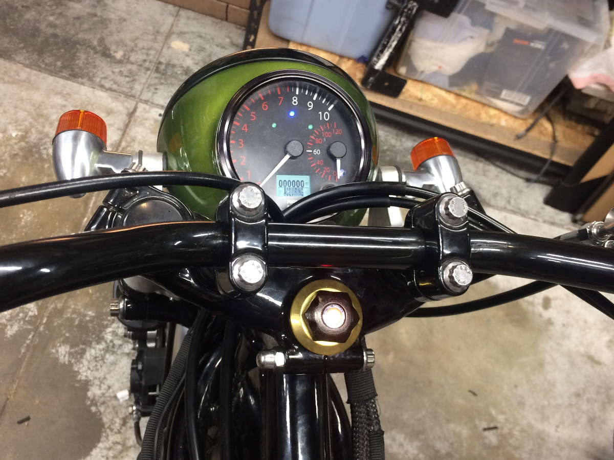
quick question on wiring the neutral indicator light;
factory wiring has 12V+ to indicator light > then to neutral switch which grounds on the engine.
this wont work in my aftermarket tach because the indicator light shares a common ground wire. I think I could use a relay to sort this out, by running 12v to the relay and then to the neutral switch to trigger the relay to send 12v to the indicator light . I don't want to use a big standard relay. This tiny LED probably needs less than 0.5 amps. will something like this work?
www.jameco.com/z/EDR201A12Z-Excel-Cell-E...m-Coil-2_106472.html
Suggestions?
Please Log in or Create an account to join the conversation.
- M_a_t_t
-
- Offline
- Sustaining Member
-
Registered
- Posts: 254
- Thanks: 41
Re: neutral switch relay
07 Apr 2018 09:31
I am not an expert in electronics, no where near. I was looking at the data sheet for that, and it shows that "switching current" (I assume that means how much to get it to switch on) is .2-.5A max. I'm not sure if the light will pull 1/2 an amp to switch it on.
Have you thought about opening the tach up and making the neutral light have its own ground?
You can use transistors as switches as well, they are typically small. Again I don't know a whole lot about electronics, but this might be another solution
www.jameco.com/shop/StoreCatalogDrillDow...Epage~SEARCH%252BNAV
83 KZ1100A (shaft)
17 Versys X 300 abs
81 kz650h1
81 kz750e2
90 Honda CBR600F (brother's)
17 Versys X 300 abs
81 kz650h1
81 kz750e2
90 Honda CBR600F (brother's)
The following user(s) said Thank You: DoctoRot
Please Log in or Create an account to join the conversation.
- loudhvx
-

- Offline
- KZr Legend
-

Registered
- Posts: 10863
- Thanks: 1622
Re: neutral switch relay
07 Apr 2018 10:56 - 07 Apr 2018 10:59
Yes, that dip mechanical relay would work, but I dont know how it would hold up to vibration.
Also, the part number ends in Z. I dont see that code in the data sheet.
Be aware, the part number shows it to be a non-diode type. A proper circuit would have a diode or rc to prevent arcing th switch. But with an integral diode you need to be very aware of the voltage polarity on the diode, otherwise it can go up in smoke. It seems the pinout is different with the diode type as well.
Wont your oil pressure light have the same problem? It would seem a tach would have a configurable indicator since so many bikes use a switched ground for things.
1981 KZ550 D1 gpz.
Kz550 valve train warning.
Other links.
Kz550 valve train warning.
Other links.
Last edit: 07 Apr 2018 10:59 by loudhvx.
The following user(s) said Thank You: DoctoRot
Please Log in or Create an account to join the conversation.
- DoctoRot
-
Topic Author
- Offline
- Sustaining Member
-
Registered
- Oh, the usual... I bowl, I drive around...
- Posts: 2618
- Thanks: 783
Re: neutral switch relay
07 Apr 2018 12:25The LEDs are soldered to a circuit board, I dont think it would be possible. That's a good point on the switching amperage.M_a_t_t wrote: I am not an expert in electronics, no where near. I was looking at the data sheet for that, and it shows that "switching current" (I assume that means how much to get it to switch on) is .2-.5A max. I'm not sure if the light will pull 1/2 an amp to switch it on.
Have you thought about opening the tach up and making the neutral light have its own ground?
I drilled and tapped the steering head bolt to hold a stand alone oil pressure light, so im good there. The Tach is by speedhut, most of their stuff is oriented towards cars. i've read the instructions and it doesn't appear that you can program the light.loudhvx wrote: Wont your oil pressure light have the same problem? It would seem a tach would have a configurable indicator since so many bikes use a switched ground for things.
the transistor route seems like a good idea, any suggestions on how to make that work?
Please Log in or Create an account to join the conversation.
- loudhvx
-
- Offline
- KZr Legend
-
Registered
- Posts: 10863
- Thanks: 1622
Re: neutral switch relay
07 Apr 2018 16:13 - 07 Apr 2018 17:37
This would probably be my first trial circuit for a transistor.
The resistors could probably be 1/4 watt without any serious problems, but 1/2 watt resistors are more robust overall, especially if you get cheap ones from China.
There is a pretty wide range of resistor values that would work for either resistor, so the exact value is not critical.
The transistor is typically rated for somewhere in the 0.5 amp range, but that is if its open to ambient air or has a fan on it. If it's buried in a silicone bubble, it's probably only safe to about .1 amp. It would probably work up to .3 amp, but its life might get shortened.
A single LED shouldn't take anywhere near those values, though. Old school LEDS would be somewhere around 0.02 to 0.03 amp. Modern indicator LEDs might take more, so make sure they don't take some insane amount like 0.3 amp or higher.
I tried to find the tach you are using, but I can't find the exact color combo you have. It looks like the closest one I can find has a high-beam indicator. Are you using that as the neutral indicator? (If so, then that is probably not configurable for a switched ground.)
I'll see if I can find any links to parts. Obviously, you will probably want more than 1 of each, especially since they are almost free.
www.jameco.com/z/PN2907A-Major-Brands-Tr...JT-TO-92_178520.html
Jameco appears to require a large minimum for 1/2 watt, 680 ohm resistors. R1 can definitely be 1/4 watt.
www.jameco.com/z/CF1-4W681JRC-Resistor-C...-Watt-5-_690822.html
www.jameco.com/z/CF1-2W222JRC-Resistor-C...-Watt-5-_661589.html
You can probably just solder this leg to leg, and then put it in a blob of 100% silicone caulk. Make sure it is 100% silicone, otherwise it will conduct. Absolutely no latex.
Test it first before siliconing.
The silicone should not be too thick so it can dissipate some heat, but make sure it's all covered for the sake of electrical insulation and water-tightness (any ambient moisture will make the solder flux corrosive over the course of years).
1981 KZ550 D1 gpz.
Kz550 valve train warning.
Other links.
Kz550 valve train warning.
Other links.
Last edit: 07 Apr 2018 17:37 by loudhvx.
The following user(s) said Thank You: DoctoRot
Please Log in or Create an account to join the conversation.
- DoctoRot
-
Topic Author
- Offline
- Sustaining Member
-
Registered
- Oh, the usual... I bowl, I drive around...
- Posts: 2618
- Thanks: 783
Re: neutral switch relay
07 Apr 2018 23:02 - 07 Apr 2018 23:02
Good call, I am using the high beam indicator light for this. Ill give your circuit a shot. Those look way smaller than a standard relay. I did try it out this afternoon with the relay and it works, I'm just running out of room to stuff a relay in there. its getting tight.
Last edit: 07 Apr 2018 23:02 by DoctoRot.
Please Log in or Create an account to join the conversation.
- cb900f
-
- Offline
- User
-

Registered
- Posts: 111
- Thanks: 30
Re: neutral switch relay
09 Apr 2018 10:07
Probably a long shot but what else is sharing the ground wire? If the 'ground' is isolated to just other lamps you could just feed it 12 volts and wire normally (assuming the lamps are bulbs or bipolar LEDs).
The following user(s) said Thank You: DoctoRot
Please Log in or Create an account to join the conversation.
- DoctoRot
-
Topic Author
- Offline
- Sustaining Member
-
Registered
- Oh, the usual... I bowl, I drive around...
- Posts: 2618
- Thanks: 783
Re: neutral switch relay
09 Apr 2018 13:32 - 09 Apr 2018 13:33
I considered that but then I would loose use of the other indicator lights because the turn signals do not use a switched ground.
Last edit: 09 Apr 2018 13:33 by DoctoRot.
Please Log in or Create an account to join the conversation.
- loudhvx
-
- Offline
- KZr Legend
-
Registered
- Posts: 10863
- Thanks: 1622
Re: neutral switch relay
09 Apr 2018 18:24
As suggested earlier, it would probably be easier to just isolate the high beam LED rather than re-configure all of the LEDs. But, obviously, either way you are hacking away at the circuit board.
1981 KZ550 D1 gpz.
Kz550 valve train warning.
Other links.
Kz550 valve train warning.
Other links.
Please Log in or Create an account to join the conversation.
- DoctoRot
-
Topic Author
- Offline
- Sustaining Member
-
Registered
- Oh, the usual... I bowl, I drive around...
- Posts: 2618
- Thanks: 783
Re: neutral switch relay
10 Apr 2018 16:12
That would void the lifetime warranty on an expensive part. I think the transistor or relay is the way to go
Please Log in or Create an account to join the conversation.
- Bama704
-

- Offline
- User
-
Registered
- Posts: 202
- Thanks: 29
Re: neutral switch relay
16 Jun 2020 12:22
Vic,
I have been looking for a solution to also use the hi beam light as my neutral light and stumbled on this post. Since I am using the Speedhut gauge as well, do you have any pointers for me before doing this? I have not used any resistors before and didn't know if you had a streamlined drawing?
I have been looking for a solution to also use the hi beam light as my neutral light and stumbled on this post. Since I am using the Speedhut gauge as well, do you have any pointers for me before doing this? I have not used any resistors before and didn't know if you had a streamlined drawing?
1977 KZ900
Carbs are late model 1975 28mm
Carbs are late model 1975 28mm
Please Log in or Create an account to join the conversation.
- DoctoRot
-
Topic Author
- Offline
- Sustaining Member
-
Registered
- Oh, the usual... I bowl, I drive around...
- Posts: 2618
- Thanks: 783
Re: neutral switch relay
16 Jun 2020 13:24
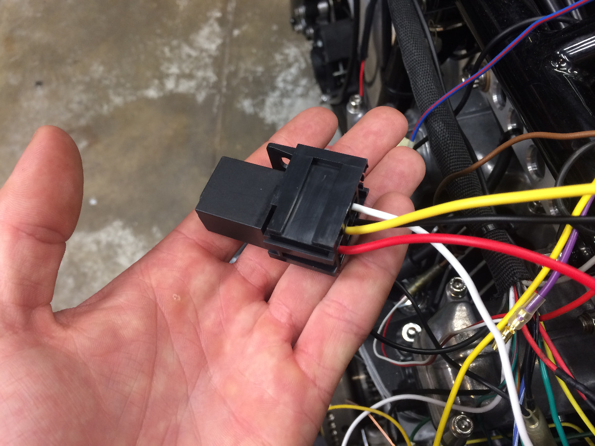
I ended up using a relay. Works fine.
This is the relay I used because its relatively small but any 4 pin relay will work.
www.amazon.com/gp/product/B003E5YBVM/ref..._title?ie=UTF8&psc=1

This is the relay I used because its relatively small but any 4 pin relay will work.
www.amazon.com/gp/product/B003E5YBVM/ref..._title?ie=UTF8&psc=1
Please Log in or Create an account to join the conversation.
Moderators: Street Fighter LTD