
De-twitching an electronic tachometer
- weeZee
-
 Topic Author
- Offline
- User
-

Registered
- Posts: 81
- Thanks: 22
De-twitching an electronic tachometer
21 Jan 2018 05:08
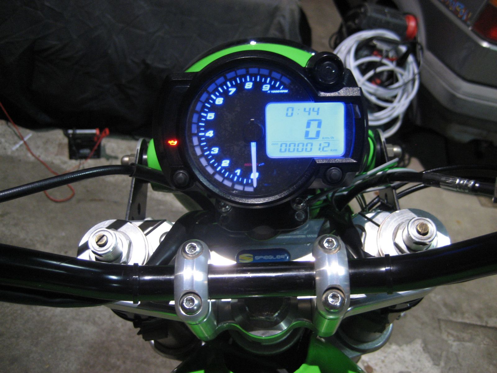
I have a Hi-Level aftermarket electronic tach on my kz650 (some modification of mount bracket is required).
The 12v coil input signal from an aftermarket electronic ignition will cause the needle to oscillate like a vacumn gauge at over 6K rpm.
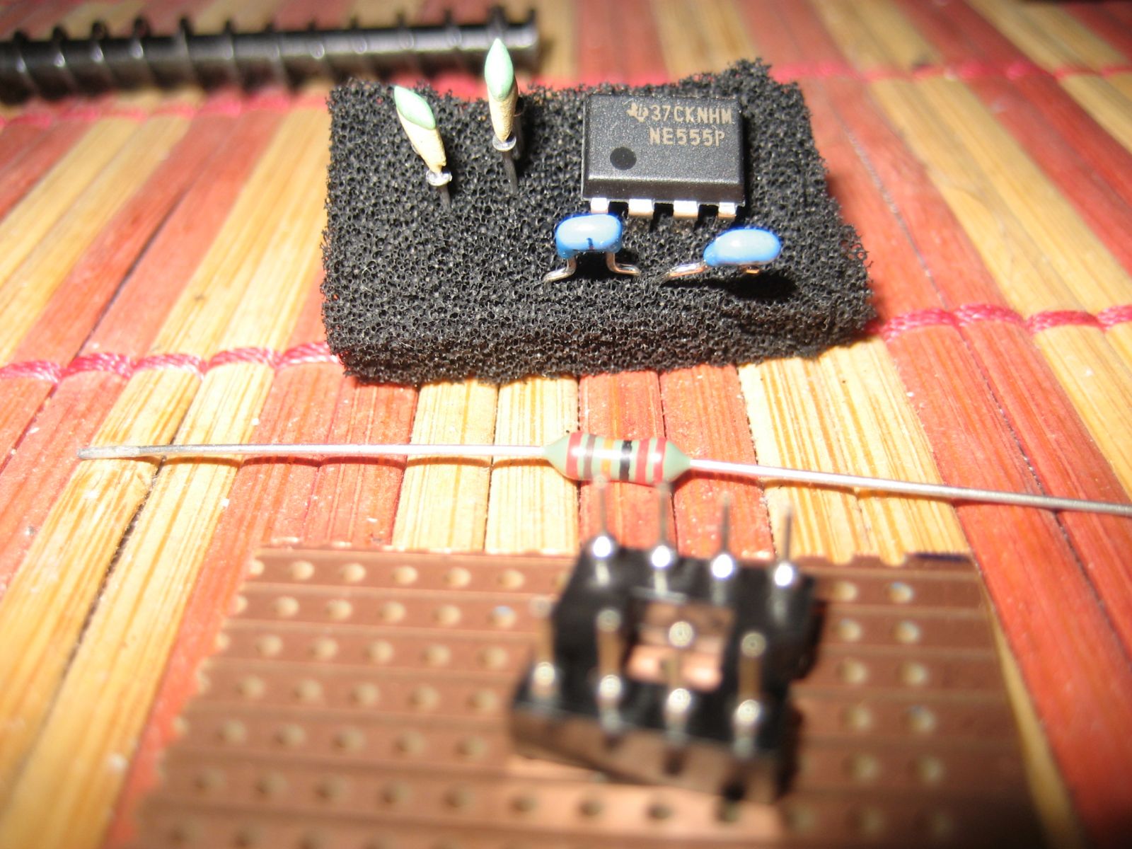
I built a small 555 timer circuit to create a squarewave signal so I could test the unit.
I can adjust the frequency and the proportion of 12v versus 0v signal (the pulse width).
The 12v coil input signal from an aftermarket electronic ignition will cause the needle to oscillate like a vacumn gauge at over 6K rpm.
I built a small 555 timer circuit to create a squarewave signal so I could test the unit.
I can adjust the frequency and the proportion of 12v versus 0v signal (the pulse width).
Please Log in or Create an account to join the conversation.
- weeZee
-
Topic Author
- Offline
- User
-
Registered
- Posts: 81
- Thanks: 22
Re: De-twitching an electronic tachometer
21 Jan 2018 05:47 - 21 Jan 2018 06:10
I found that a 2.5 millisecond pulse gave a steady reading throughout all the RPM (or frequency range).
If the 12 volt pulse was longer, or shorter than roughly 2.5mS, the unit would either behave erratically at higher RPM, or would not cover the full RPM range.
The solution is to build a circuit that receives a pulse of whatever width, and outputs a neat 2.5mS pulse.
The bog-standard circuit is a 555-based monostable using a 220K ohm resistor and a 0.01uF capacitor.
The other decoupling capacitors are 0.1uF.
Last edit: 21 Jan 2018 06:10 by weeZee.
Please Log in or Create an account to join the conversation.
- weeZee
-
Topic Author
- Offline
- User
-
Registered
- Posts: 81
- Thanks: 22
Re: De-twitching an electronic tachometer
21 Jan 2018 08:25
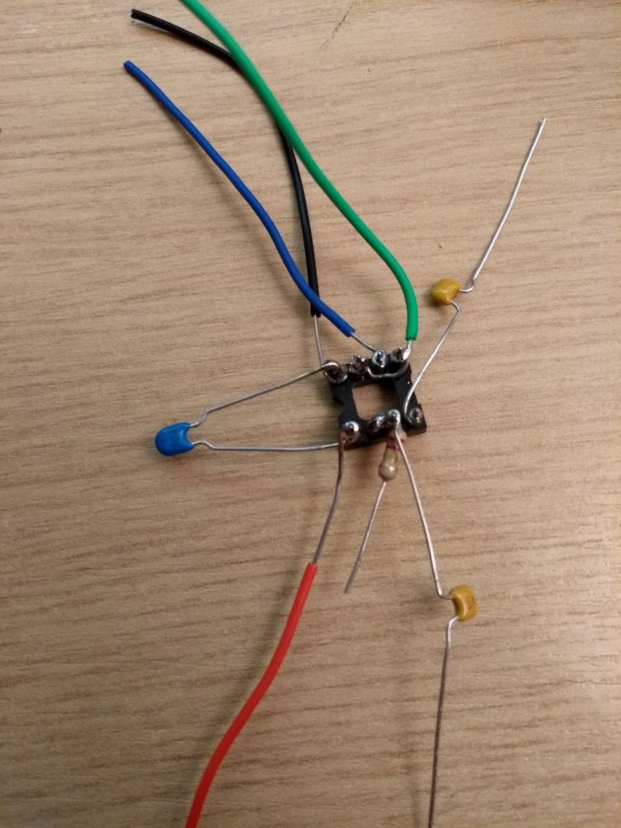
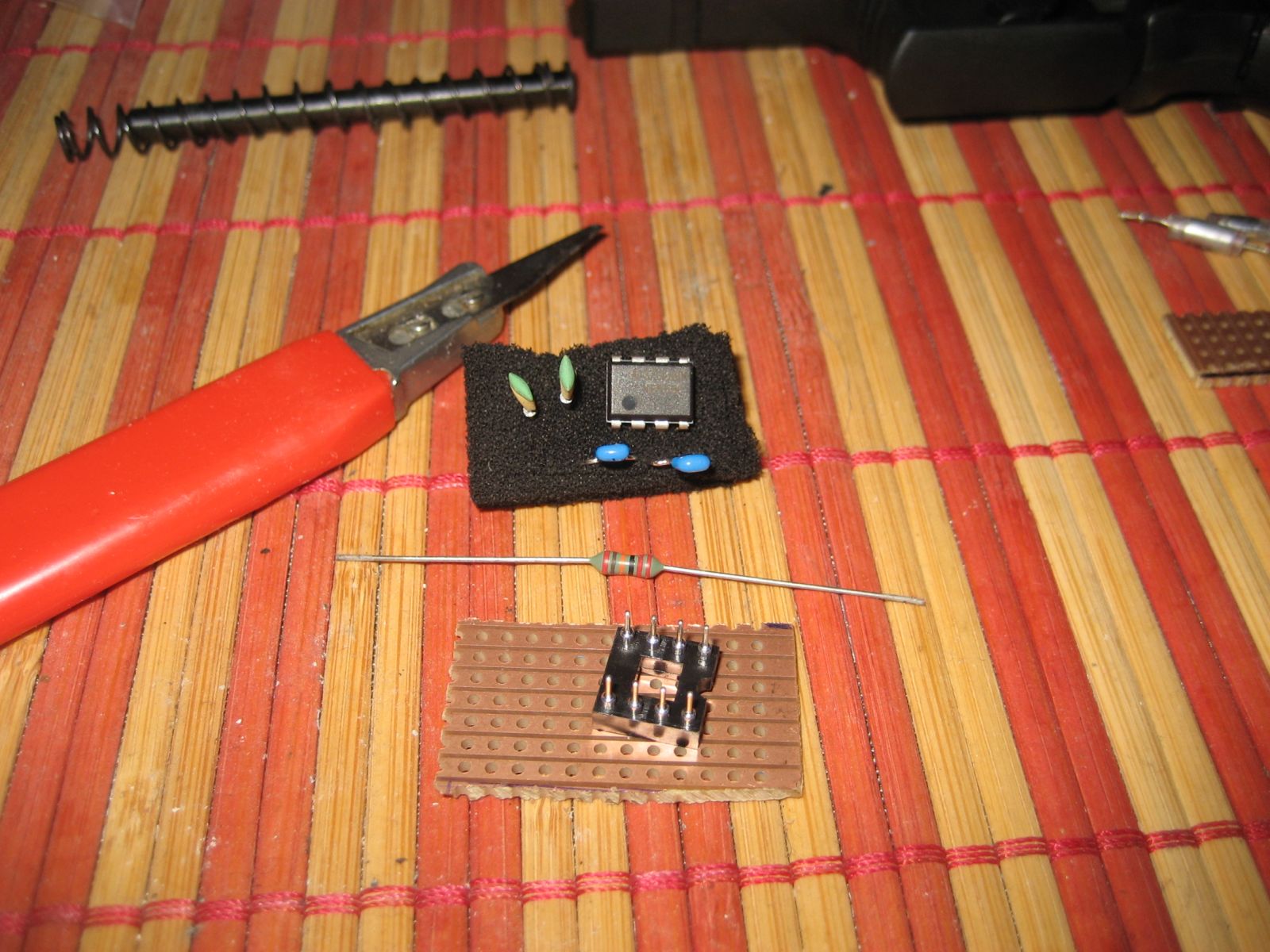
The circuit is put together with "dead-bug" construction.
Please Log in or Create an account to join the conversation.
- weeZee
-
Topic Author
- Offline
- User
-
Registered
- Posts: 81
- Thanks: 22
Please Log in or Create an account to join the conversation.
- weeZee
-
Topic Author
- Offline
- User
-
Registered
- Posts: 81
- Thanks: 22
Re: De-twitching an electronic tachometer
21 Jan 2018 08:27
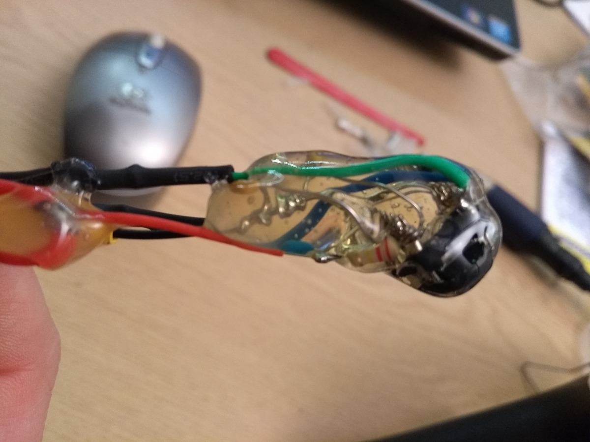
And sealed in hot-glue. Cheap, fast, nasty, what's not to like?
Please Log in or Create an account to join the conversation.
- Scirocco
-
- Offline
- Premium Member
-

Registered
- Never change a running system
- Posts: 4397
- Thanks: 2260
Re: De-twitching an electronic tachometer
27 Jan 2018 12:46
Hello weeZee
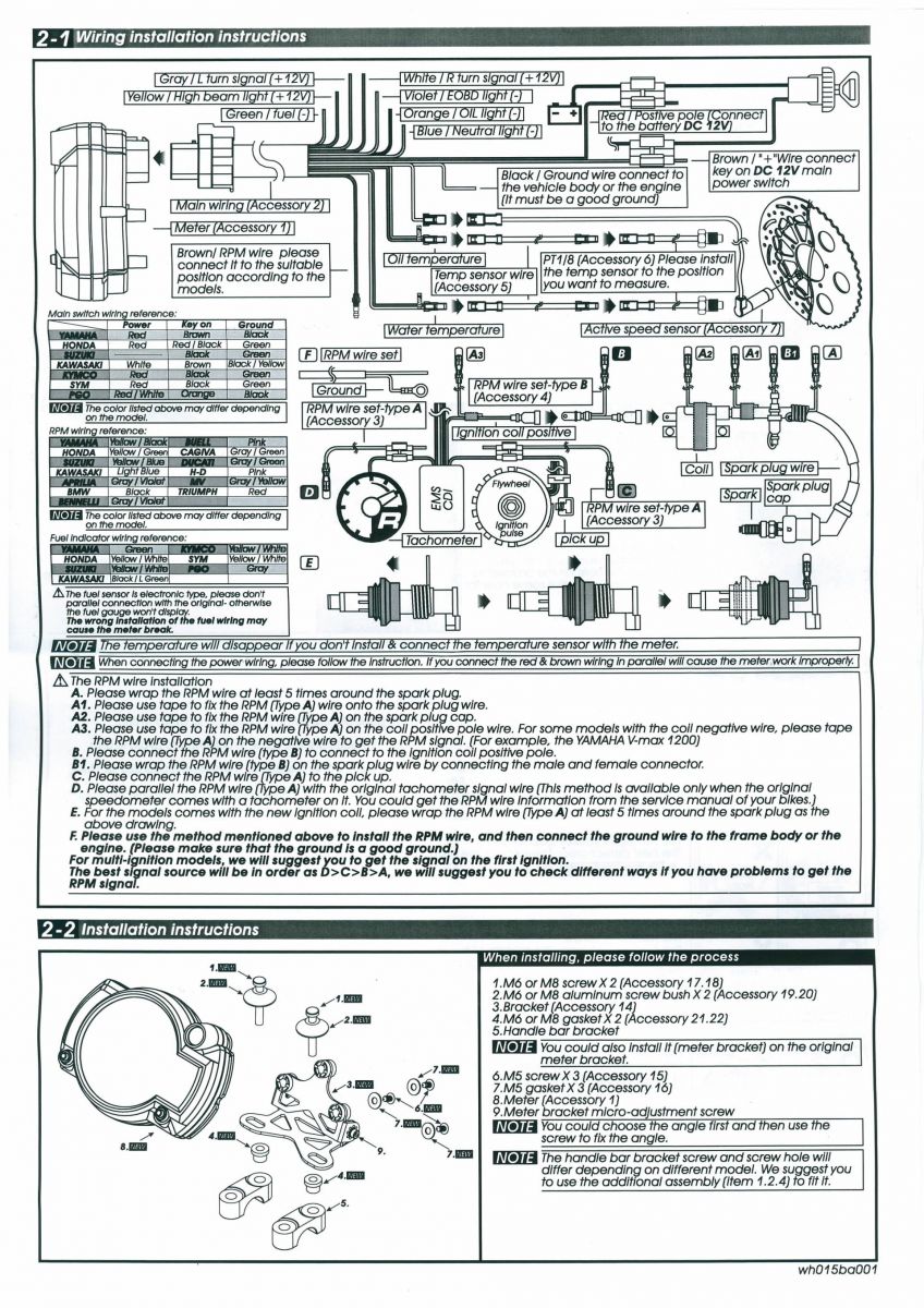
Can you make a more detailed wiring diagram, i want to made a De-twitching board for my KOSO RX2N+ GP Style too.
Which wire comes and goes to +/-/signal in/out ???
Want to get a steady reading throughout all the RPM, (shaking needle @ 4000 rpm)
Many thanks in advance
Michael
Can you make a more detailed wiring diagram, i want to made a De-twitching board for my KOSO RX2N+ GP Style too.
Which wire comes and goes to +/-/signal in/out ???
Want to get a steady reading throughout all the RPM, (shaking needle @ 4000 rpm)
Many thanks in advance
Michael
My 1975 Z 1 B 900 Project
www.kzrider.com/forum/11-projects/605133...ears-deep-sleep-mode
www.kzrider.com/forum/11-projects/605133...ears-deep-sleep-mode
Please Log in or Create an account to join the conversation.
- loudhvx
-

- Offline
- KZr Legend
-

Registered
- Posts: 10863
- Thanks: 1622
Re: De-twitching an electronic tachometer
27 Jan 2018 13:12
One problem with the stock electronic ignition is false triggers due to magnetic crosstalk in the pickups. It's not electrical crosstalk, it's magnetic, so a filter won't really get rid of it. The solution is to use a slightly less sensitive igniter like the HEI modules or a module using discrete parts. Another solution is to attenuate the pickup signal after the motor is running. These options will get rid of the false triggers.
A 555 one-shot timer won't really get rid of the false triggers since the recovery time will be short enough to allow a false trigger to produce a false one-shot signal.
You can see the false triggers if you put a timing light on the rotor while the bike is running. You will see the rotor, along with a ghost image of the rotor 180 degrees rotated. Sometimes only one of the circuits will have the false triggers, in which case, if you run the tach signal from the clean pickup signal you can get rid of the problem without any extra parts or modifications.
The Kz pickups have a wide range of sensitivity. I believe this is because of differences in the magnets used on the pickups. So some will have a lot of false triggers while other sets my have none.
Here's the HEI version which seems far more immune to false triggers than the stock igniter.
s3.amazonaws.com/gpzweb/Ignition/GPZgmHEImod.html
Here's one made from discrete parts.
s3.amazonaws.com/gpzweb/Ignition/GPZignitionMod.html
I still use both on different bikes and they still work fine even after nearly 20 years.
1981 KZ550 D1 gpz.
Kz550 valve train warning.
Other links.
Kz550 valve train warning.
Other links.
Please Log in or Create an account to join the conversation.
- Scirocco
-
- Offline
- Premium Member
-
Registered
- Never change a running system
- Posts: 4397
- Thanks: 2260
Re: De-twitching an electronic tachometer
27 Jan 2018 14:44
Thanks loudhvx for the input, will try to get a useful signal from my Dyna-S pickup next.
Have tried all technical possibilities to get a clear signal (plus from one stator wire).
But for the plan "B" i will build and test the De-twitching circuit board.
Have tried all technical possibilities to get a clear signal (plus from one stator wire).
But for the plan "B" i will build and test the De-twitching circuit board.
My 1975 Z 1 B 900 Project
www.kzrider.com/forum/11-projects/605133...ears-deep-sleep-mode
www.kzrider.com/forum/11-projects/605133...ears-deep-sleep-mode
Please Log in or Create an account to join the conversation.
- loudhvx
-
- Offline
- KZr Legend
-
Registered
- Posts: 10863
- Thanks: 1622
Re: De-twitching an electronic tachometer
27 Jan 2018 17:01 - 27 Jan 2018 17:10
The Dyna S is a totally different beast. It is essentially an on-off switch for the coil, so the crosstalk etc mentioned for the stock ignition should not be present with the Dyna S.
The Dyna S has other issues related to electronic-tach usage. These problems relate to the fact that the dwell angle is over 300 degrees of crank rotation.
One problem related to having the extra-long dwell is that you need an adapter circuit if you are combining pulses from both coils to create the tach signal.
Another issue is that with such a short interval for the coil to fire, some tachs won't recognize pulse from the Dyna S at higher RPMs.
If you are only using one coil to create the tach signal (as the instructions to your tach seem to indicate), and the tach jitter is due to the long dwell pulse, then a 555 one-shot circuit (sometimes called a debounce circuit) might fix it. To be stable, though, the supply will have to be filtered against alternator noise and ignition spikes on the battery voltage. When a coil fires, it no longer uses battery current so the battery voltage tends to increase briefly. There should be many 555 debounce circuit diagrams available on the internet. You will want to select a signal-high time of about 3 msec or so. That will equate to a 180 degree dwell at 10,000 rpm. That is, the signal will be a 50% duty square wave at 10,000 rpm.
If you can't find one, I can draw one.
One your tach, it looks like you would connect the tach wire to the negative terminal of the coil. That is the coil terminal that is connected to the Dyna S. I assume that is what you have tried first.
1981 KZ550 D1 gpz.
Kz550 valve train warning.
Other links.
Kz550 valve train warning.
Other links.
Last edit: 27 Jan 2018 17:10 by loudhvx.
The following user(s) said Thank You: weeZee
Please Log in or Create an account to join the conversation.
- DoctoRot
-
- Offline
- Sustaining Member
-

Registered
- Oh, the usual... I bowl, I drive around...
- Posts: 2621
- Thanks: 784
Re: De-twitching an electronic tachometer
29 Jan 2018 10:15
I had this issue on my speedhut tach running a dyna s ignition. it picks up from one coil. I called them up and they sent me a "noise filter" which i wired in and it seemed to fix the problem.
The following user(s) said Thank You: Scirocco
Please Log in or Create an account to join the conversation.
- weeZee
-
Topic Author
- Offline
- User
-
Registered
- Posts: 81
- Thanks: 22
Re: De-twitching an electronic tachometer
06 Feb 2018 06:15 - 06 Feb 2018 06:19
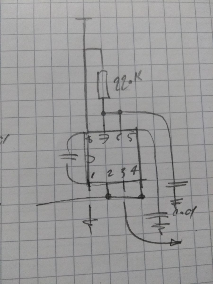
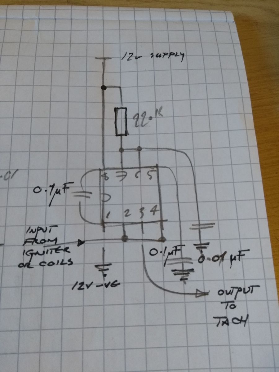
Sorry about delay and rough diagram, I've annotated it some more here. The downward facing arrow symbols represent bike negative, so all joined together. Purists will complain that the 555 schematic symbol is based on the pin-out rather than the schematic 555 representation. It's a monostable 555 implementation, so you still need a clean signal for it to work, if there are ghost signals or alternator noise spikes as mentioned earlier, it will cause false triggering. I'm pretty sure the Dyna signal width is adequate to trigger the 555. Other folks with noisy signals can benefit from a simple low-pass filter mod.
Last edit: 06 Feb 2018 06:19 by weeZee.
The following user(s) said Thank You: Scirocco
Please Log in or Create an account to join the conversation.
- weeZee
-
Topic Author
- Offline
- User
-
Registered
- Posts: 81
- Thanks: 22
Re: De-twitching an electronic tachometer
06 Feb 2018 06:29 - 06 Feb 2018 06:29
Going to put a quick note here. It's also possible to get a beautifully clean signal from the alternator output, but the voltage can go up to 70V on a kz. I would guess that an hefty Zener and resistor crowbar circuit should provide enough for a few mA without too much load/heat. This note is awaiting further wisdom rather than providing sound advice.
Last edit: 06 Feb 2018 06:29 by weeZee.
Please Log in or Create an account to join the conversation.
Moderators: Street Fighter LTD