1977 KZ400 Wiring Driagram Approval
- chiefkeef88
-
Topic Author
- Offline
- User
-

Registered
- Posts: 3
- Thanks: 0
1977 KZ400 Wiring Driagram Approval
07 Sep 2015 07:56
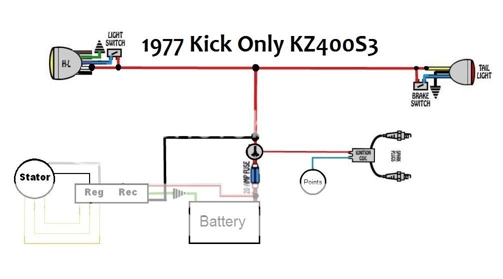
Hello all, my name is Scott. I'm a soldier based out of the southwest and recently inherited a half way finished KZ400 project. One of the many hurdle's is doing a complete rewiring. I have searched and posted on another KZ forum which now appears to cease to exist and got no replies, so I figured I would try this one and see what you all thought. Attached is a wiring diagram that I have 'frankensteined' from many others I have found online as well as this rough guide on bike exif:
www.bikeexif.com/motorcycle-wiring
. Please if you could, look over it real quick and let me know what you think needs to be fixed or changed. Some things to consider;
1. It's kick start only 1977 KZ400S3
2. Only running head and tail light on the accesories circuit for now. Considering adding a horn/speedo illum soon
3. Combined Rick's Rec/Reg
4. Still running points system
5. Dyna Coil
6. 3 position key ignition
Again please let me know what you think. Im here to learn/not blow any of my parts haha. Thanks in advance.
- Scott
Please Log in or Create an account to join the conversation.
- loudhvx
-

- Offline
- KZr Legend
-

Registered
- Posts: 10863
- Thanks: 1622
Re: 1977 KZ400 Wiring Driagram Approval
07 Sep 2015 13:00
That does not look right. The green wire is typically the field coil wire, and the white wire is the rectifier output, so if sticking with stock wiring colors, those two wires should have their colors swapped.
I can draw a simplified diagram if you have a diagram (I will look to see if I have one already).
I can draw a simplified diagram if you have a diagram (I will look to see if I have one already).
1981 KZ550 D1 gpz.
Kz550 valve train warning.
Other links.
Kz550 valve train warning.
Other links.
Please Log in or Create an account to join the conversation.
- loudhvx
-

- Offline
- KZr Legend
-

Registered
- Posts: 10863
- Thanks: 1622
Re: 1977 KZ400 Wiring Driagram Approval
07 Sep 2015 14:05 - 07 Sep 2015 14:06
It's on the last page of the Mattylight thread.
kzrider.com/forum/4-electrical/172746-19...ght?start=360#689038
kzrider.com/forum/4-electrical/172746-19...ght?start=360#689038
1981 KZ550 D1 gpz.
Kz550 valve train warning.
Other links.
Kz550 valve train warning.
Other links.
Last edit: 07 Sep 2015 14:06 by loudhvx.
Please Log in or Create an account to join the conversation.
- chiefkeef88
-
Topic Author
- Offline
- User
-

Registered
- Posts: 3
- Thanks: 0
Re: 1977 KZ400 Wiring Driagram Approval
07 Sep 2015 18:34 - 07 Sep 2015 18:46
Hey loudhvx, thanks a ton for the reply, I have almost zero wiring leftover stock from the original bike harness, every component and every piece of the 'harness' (really its just one or two wires at any given point on the frame) is new (except the wires coming from the stator). So the wiring is either black (which I used to make the battery/ignition connections) or its the colors coming off of the component. In this case the Rick's Rec/Reg came with the folliwing 'manual';
BUNDLE 1
White/Red to Battery Positive
Green to Battery negative (Ground)
Black to 12 volt power source after key is switched on
BUNDLE 2
3 Yellow to Stator
Black to One side of field or brush 1
White to Other side of field or brush 2
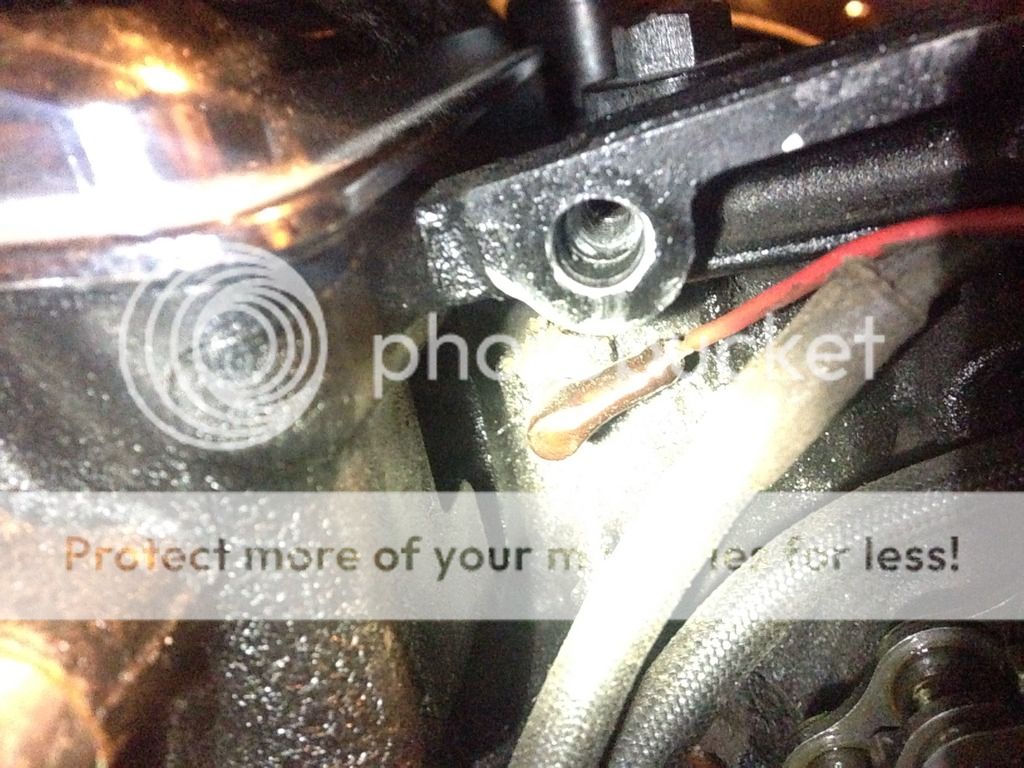
As far as what is coming out of the bike I've got three yellow , 1 green, one gray, one black, and one red. I know the three yellow obviously, and I am 90% sure that the red is coming from the neutral indicator switch on the left side of the motor near the sproket. However not sure what the green, grey, and black are from the bike.
Last edit: 07 Sep 2015 18:46 by chiefkeef88.
Please Log in or Create an account to join the conversation.
- loudhvx
-

- Offline
- KZr Legend
-

Registered
- Posts: 10863
- Thanks: 1622
Re: 1977 KZ400 Wiring Driagram Approval
08 Sep 2015 05:33 - 08 Sep 2015 05:45
Ah, ok, well that would explain it. The wiring colors are for another manufacturer... probably Honda.
There isn't really any reason to have a 3 position ignition switch as you have it drawn, but if you wanted, you could probably eliminate the headlight on/off switch by using the ignition switch in an unconventional way. You could have one position for running the bike with the headlight off, and another position for running the bike with headlight on.
There isn't really any reason to have a 3 position ignition switch as you have it drawn, but if you wanted, you could probably eliminate the headlight on/off switch by using the ignition switch in an unconventional way. You could have one position for running the bike with the headlight off, and another position for running the bike with headlight on.
1981 KZ550 D1 gpz.
Kz550 valve train warning.
Other links.
Kz550 valve train warning.
Other links.
Last edit: 08 Sep 2015 05:45 by loudhvx.
Please Log in or Create an account to join the conversation.
- chiefkeef88
-
Topic Author
- Offline
- User
-

Registered
- Posts: 3
- Thanks: 0
Re: 1977 KZ400 Wiring Driagram Approval
08 Sep 2015 08:48
I plan on keeping the headlight always on, so position 1 is off, position 2 is accessories + lights and position 3 is ignition + everything. On the ignition itself it has one spot labeled battery, one labeled IG, and the other I believe is L which I assumed lights/accessories? I don't now if its supposed to work this way, but thats what I guesstimated.
Would you know anything about the wires coming off the stator and what those colors are indicating? I'm confident about the reg/rec obviously, but not so much about what is what in the bundle coming from the motor.
Would you know anything about the wires coming off the stator and what those colors are indicating? I'm confident about the reg/rec obviously, but not so much about what is what in the bundle coming from the motor.
Please Log in or Create an account to join the conversation.
- loudhvx
-

- Offline
- KZr Legend
-

Registered
- Posts: 10863
- Thanks: 1622
Re: 1977 KZ400 Wiring Driagram Approval
08 Sep 2015 10:26
The alternator you have is called an "excited-field" type. All that means is that the magnetism comes from a big electromagnet instead of a permanent magnet. The electromagnet is called the field coil.
Most KZ's use a spinning permanent magnet as the flywheel. As the magnetic field rotates past the stator, an AC voltage is created in the stator. The output of the stator is the 3 yellow wires.
Your bike uses a spinning pole-inverter as the flywheel. The electromagnet is attached to the alternator cover, and the pole-inverter spins to create a rotation in the magnetic field. This rotating magnetic field creates a 3-phase AC voltage (and current) on the three yellow output wires.
Originally, the electromagnet gets its power from the green output wire of the regulator. The black wire of the electromagnet is ground. In this way, the regulator controls the intensity of the magnetic field by controlling the voltage on the green wire.
Sometimes, other models, or aftermarket regulators, may apply 12v to the positive side of the electromagnet, and the regulator will control the ground side of the electromagnet. It can be done either way, and there isn't really an advantage either way, but it is important to know which way it is for troubleshooting.
On your regulator, it's possible the black wire to the field coil (electromagnet) is permanently 12v, and the regulator is controlling the ground side on the white wire. Or it's possible the black wire varies the 12v supply and the white wire is just grounded. Or it's possible the colors are the reverse of the above. So there are actually 4 possibilities to the aftermarket wiring to the field coil. You would need a volt meter with the bike running, to figure out which way it is.
The three yellows from the alternator are the output of the stator, which are AC, and go to the rectifier to be converted to DC. The regulator detects the DC output voltage to determine the amount of voltage to apply to the field coil.
1981 KZ550 D1 gpz.
Kz550 valve train warning.
Other links.
Kz550 valve train warning.
Other links.
Please Log in or Create an account to join the conversation.
- alinaaseh
-
- Offline
- User
-

Registered
- Posts: 19
- Thanks: 1
Re: 1977 KZ400 Wiring Driagram Approval
13 Apr 2016 14:29
chiefkeef88,
The red wire, as you guessed, is connected to the neutral switch. The grey wire is connected to the oil pressure switch.
The red wire, as you guessed, is connected to the neutral switch. The grey wire is connected to the oil pressure switch.
1976 KZ400 D3
Ft. Collins, CO
Ft. Collins, CO
Please Log in or Create an account to join the conversation.
- bcfox0630
-
- Offline
- User
-

Registered
- Posts: 11
- Thanks: 0
Re: 1977 KZ400 Wiring Driagram Approval
09 Nov 2022 23:44
Not sure if you figured out the Rick's rag wreck combination but I had the same problem and I finally got through with it and it was because the wires were labeled wrong and some of them weren't having the right sleeves on them but if you need more information just reply to the message and I can give you a breakdown
Please Log in or Create an account to join the conversation.
- TexasKZ
-

- Offline
- Platinum Member
-

Registered
- Posts: 8124
- Thanks: 2639
Re: 1977 KZ400 Wiring Driagram Approval
10 Nov 2022 15:04
bcfox0630,
The member who started this old thread has not logged in since 2016, and Lou died recently, so you are not likely to get a response.
The member who started this old thread has not logged in since 2016, and Lou died recently, so you are not likely to get a response.
1982 KZ1000 LTD parts donor
1981 KZ1000 LTD awaiting resurrection
2000 ZRX1100 not ridden enough
www.kzrider.com/11-projects/620336-anoth...uild-thread?start=24
1981 KZ1000 LTD awaiting resurrection
2000 ZRX1100 not ridden enough
www.kzrider.com/11-projects/620336-anoth...uild-thread?start=24
Please Log in or Create an account to join the conversation.
Moderators: Street Fighter LTD


