
Quick question about HEI mod. (Urgent)
- mushroom_toy
-
 Topic Author
- Offline
- User
- Posts: 22
- Thanks: 0
Quick question about HEI mod. (Urgent)
27 Jan 2009 19:26
Alrigth Im putting everything together but i have a quick question. According to the diagram im supposed to run the diodes, resistor, connect them together and run them to the connected red and blue pickup wires?
If this is the case wouldnt this ground the positive out?
If this is the case wouldnt this ground the positive out?
Please Log in or Create an account to join the conversation.
- mushroom_toy
-
Topic Author
- Offline
- User
- Posts: 22
- Thanks: 0
Re: Quick question about HEI mod. (Urgent)
27 Jan 2009 23:09
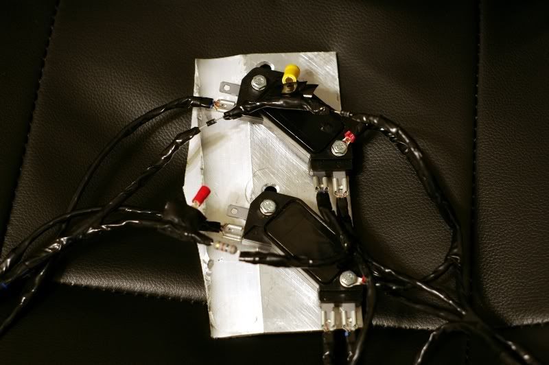
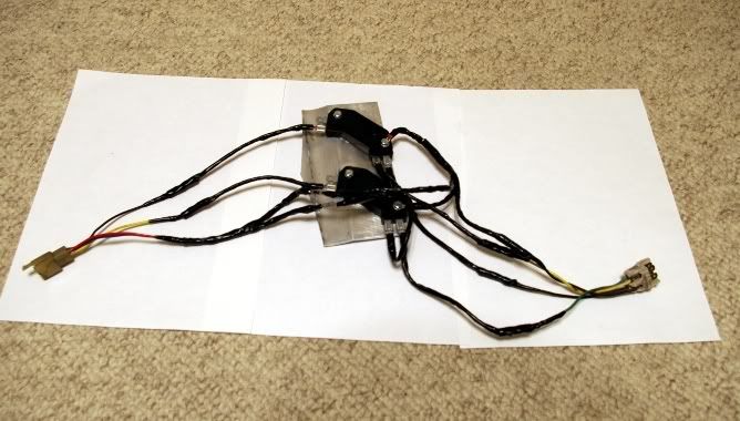
OK well does this look right guys? I wired the diodes, and the resistor into the red/blue pickup wires, and they are indicated in the pictures with a yellow terminal taped to the diodes and a red one taped to the resistor. Is this right?
Please Log in or Create an account to join the conversation.
- loudhvx
-

- Offline
- KZr Legend
- Posts: 10864
- Thanks: 1618
Re: Quick question about HEI mod. (Urgent)
27 Jan 2009 23:41 - 27 Jan 2009 23:42
mushroom_toy wrote:
The red and blues pickup wires are being tied to a 1.39 volt source created by the resistor and two diodes. This 1.39 volts is putting a DC bias voltage on the pickups. The black and yellow wires will have an AC signal in addition to the DC bias.

The positive pickup wires are the black and yellow wires.Alrigth Im putting everything together but i have a quick question. According to the diagram im supposed to run the diodes, resistor, connect them together and run them to the connected red and blue pickup wires?
If this is the case wouldnt this ground the positive out?
The red and blues pickup wires are being tied to a 1.39 volt source created by the resistor and two diodes. This 1.39 volts is putting a DC bias voltage on the pickups. The black and yellow wires will have an AC signal in addition to the DC bias.
1981 KZ550 D1 gpz.
Kz550 valve train warning.
Other links.
Kz550 valve train warning.
Other links.
Attachments:
Last edit: 27 Jan 2009 23:42 by loudhvx.
Please Log in or Create an account to join the conversation.
- mushroom_toy
-
Topic Author
- Offline
- User
- Posts: 22
- Thanks: 0
Re: Quick question about HEI mod. (Urgent)
27 Jan 2009 23:48
Thanks for the reply. You seem like a very smart guy especially for coming up with the idea. ")
Can you tell by the pictures if that looks rigtht to you?
Your explanation makes more sense to me know. Thanks.
Can you tell by the pictures if that looks rigtht to you?
Your explanation makes more sense to me know. Thanks.
Please Log in or Create an account to join the conversation.
- loudhvx
-
- Offline
- KZr Legend
- Posts: 10864
- Thanks: 1618
Re: Quick question about HEI mod. (Urgent)
27 Jan 2009 23:53
mushroom_toy wrote:
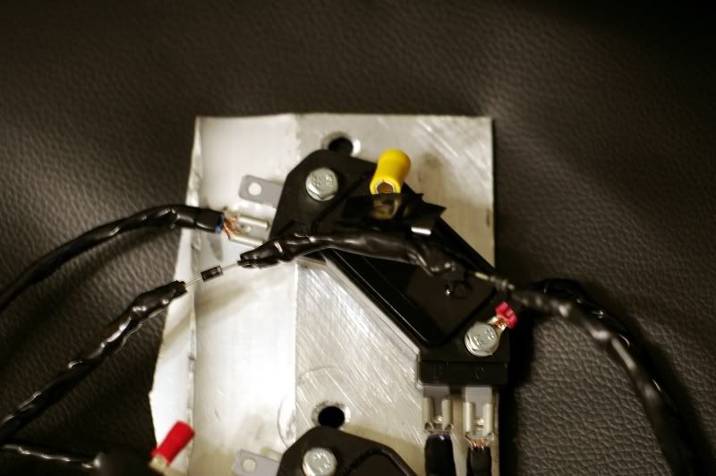
Unfortunately, I can't really tell what's happening with all that electrical tape. Are you sure it's a 1 watt resistor there? For some reason it looks more like a 1/2 watt to me, but that could just be because of the camera.
I'm more worried about the legs of the resistor and diodes breaking off. They are not really meant to be mounted that way. I would recommend soldering them closer together and taping them into a little bundle so their legs won't vibrate off. Then run wires from the bundle to where they need to go.
Why is there a red connector just floating without a wire attached to it?
OK well does this look right guys? I wired the diodes, and the resistor into the red/blue pickup wires, and they are indicated in the pictures with a yellow terminal taped to the diodes and a red one taped to the resistor. Is this right?
Unfortunately, I can't really tell what's happening with all that electrical tape. Are you sure it's a 1 watt resistor there? For some reason it looks more like a 1/2 watt to me, but that could just be because of the camera.
I'm more worried about the legs of the resistor and diodes breaking off. They are not really meant to be mounted that way. I would recommend soldering them closer together and taping them into a little bundle so their legs won't vibrate off. Then run wires from the bundle to where they need to go.
Why is there a red connector just floating without a wire attached to it?
1981 KZ550 D1 gpz.
Kz550 valve train warning.
Other links.
Kz550 valve train warning.
Other links.
Please Log in or Create an account to join the conversation.
- loudhvx
-
- Offline
- KZr Legend
- Posts: 10864
- Thanks: 1618
Re: Quick question about HEI mod. (Urgent)
27 Jan 2009 23:59
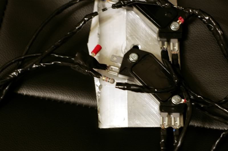
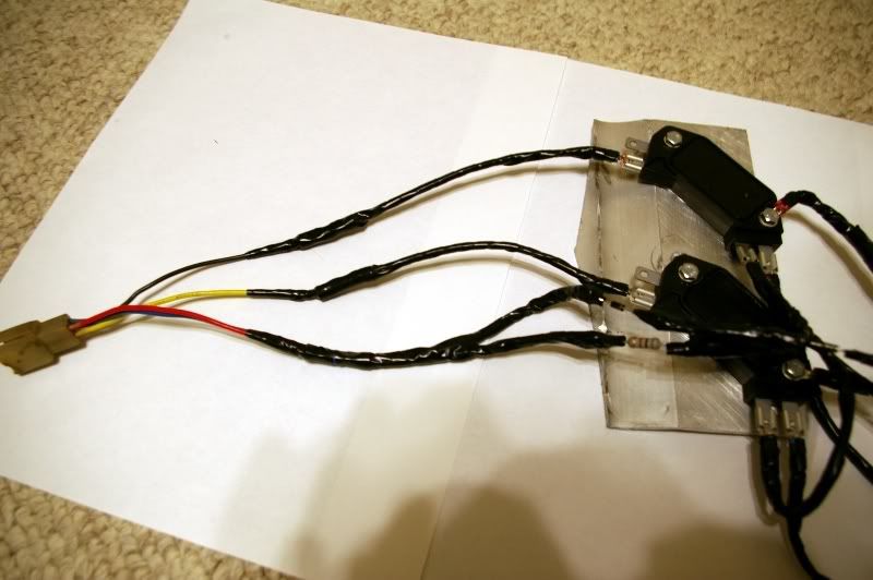
By the way, I'm glad you are trying the mod. I'll try to help all I can. Can you maybe peel back or cut off some of the tape so I can see the wire colors? That would help me trace them in the pictures.
1981 KZ550 D1 gpz.
Kz550 valve train warning.
Other links.
Kz550 valve train warning.
Other links.
Please Log in or Create an account to join the conversation.
- mushroom_toy
-
Topic Author
- Offline
- User
- Posts: 22
- Thanks: 0
Re: Quick question about HEI mod. (Urgent)
28 Jan 2009 00:01
Yeah its a 1 watt. I made sure to follow your parts list for the exact radioshack #s. Part # on my pack of resistors is 271-152. I soldered the diodes with a short piece of wire in between then bent most of the arm back on the wire before I soldered. Im gonna be wrapping em up better just wanted to make sure that I had everything right at first. It will be fine to wrap them up in tape correct? The resistor as well? That connector both the yellow and red are taped to the harness to distinguish between the diodes and resister. Just taped there for photo references.
Please Log in or Create an account to join the conversation.
- loudhvx
-
- Offline
- KZr Legend
- Posts: 10864
- Thanks: 1618
Re: Quick question about HEI mod. (Urgent)
28 Jan 2009 00:05
Ok then. Yes the resistor can be taped. I did the same on mine and it's worked for several years now. I'm still having trouble tracing the wires on your photos, though.

1981 KZ550 D1 gpz.
Kz550 valve train warning.
Other links.
Kz550 valve train warning.
Other links.
Attachments:
Please Log in or Create an account to join the conversation.
- mushroom_toy
-
Topic Author
- Offline
- User
- Posts: 22
- Thanks: 0
Re: Quick question about HEI mod. (Urgent)
28 Jan 2009 00:14
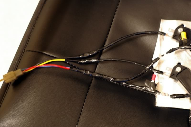
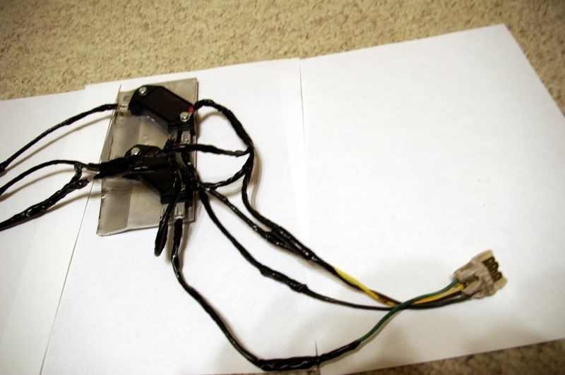
Alright sorry about that. yeah I think all the wires are ran correctly as I triple checked all of them as I was reading and looking at the diagrams. I took a couple of better pics (i hope) the lighting in my room hates my dslr. The main concern I had was with the diodes and resistor but after the explaining I think I should be good to go. I would have peeled back more tape, but i wanted to make sure they were taped up real good before I start the bundling layer.  I tried to seperate the wires a bit.
I tried to seperate the wires a bit.
Please Log in or Create an account to join the conversation.
- loudhvx
-
- Offline
- KZr Legend
- Posts: 10864
- Thanks: 1618
Re: Quick question about HEI mod. (Urgent)
28 Jan 2009 00:28
I think it looks right, but I can't swear to it.
KZrider forum seems to be having difficulties right now. It's loading really slowly and starting to give error messages like site not found etc., so it may crash soon.
KZrider forum seems to be having difficulties right now. It's loading really slowly and starting to give error messages like site not found etc., so it may crash soon.
1981 KZ550 D1 gpz.
Kz550 valve train warning.
Other links.
Kz550 valve train warning.
Other links.
Please Log in or Create an account to join the conversation.
- mushroom_toy
-
Topic Author
- Offline
- User
- Posts: 22
- Thanks: 0
Re: Quick question about HEI mod. (Urgent)
28 Jan 2009 00:35
Its doing the same for me. im gonna get thi thing bundled up and see how she does tomorrow. ill let ya know how things go. Thanks for the idea.
Please Log in or Create an account to join the conversation.
- loudhvx
-
- Offline
- KZr Legend
- Posts: 10864
- Thanks: 1618
Re: Quick question about HEI mod. (Urgent)
28 Jan 2009 00:52
Check your other thread. There is definitely something wrong with the power going to the coils. It should be the same as battery voltage when the key is on. You are losing it somewhere.. mostlikely in the ignition switch, kill switch, fuse box or even a connector.
If the HEI mod is done correctly, you can temporarily hardwire the positive side of the coils to the battery positive terminal. But use a fuse in line for safety.
If the HEI mod is done correctly, you can temporarily hardwire the positive side of the coils to the battery positive terminal. But use a fuse in line for safety.
1981 KZ550 D1 gpz.
Kz550 valve train warning.
Other links.
Kz550 valve train warning.
Other links.
Please Log in or Create an account to join the conversation.