vacuum & fuel line house routing
- 94yj
-
Topic Author
- Offline
- User
-

Registered
- Posts: 13
- Thanks: 0
vacuum & fuel line house routing
02 May 2006 17:35
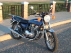
i have a 1980 kz 650 ltd and i need to know where the vacuum line port from the rear of the fuel petcock is routed to on the engine as the person i got the bike from had all of the hoses gone also does anyone have a picture of the hose routing on the air intake injection system or of the fuel system so i can see what else i am missing
thanks
Post edited by: 94yj, at: 2006/05/02 21:07
thanks
Post edited by: 94yj, at: 2006/05/02 21:07
Please Log in or Create an account to join the conversation.
- N0NB
-

- Offline
- User
-

Registered
- Blue handles better
- Posts: 1811
- Thanks: 19
Re: vacuum & fuel line house routing
02 May 2006 19:43
For reference, when you are seated on the bike #1 cylinder (and carb) are on your left and everything counts across left to right.
On the left side of the #2 carb you should see two brass nipples. The one closest to the engine is connected to the smaller nipple on your petcock.
The more rearward one (#4 carb has a nipple in a similar location) is the vent for the bowls and has its hose routed toward the rear of the bike up and over the front of the airbox and then down between the airbox and the frame tube (do the same for #4). These hoses must be open so the fuel in the bowls remains at atmospheric pressure.
The air injection vacuum switch is controlled by the lines that connect to the pipes on the #1 and #4 carb holder boots between the carbs and the engine head. Note that the #2 and #3 pipes are capped off. These lines go up to a tee and then one line to the vacuum switch. Should the vacuum switch ever be removed the pipes on #1 and #4 must be capped as well. These pipes are where a synchronizing meter is connected.
HTH,
- Nate >>
Nate
Nates vintage bike axiom: Riding is the reward for time spent wrenching.
Murphys corollary: Wrenching is the result of time spent riding.
1979 KZ650 (Complete!)
1979 KZ650 SR (Sold!)
1979 KL250 (For sale)
1994 Bayou 400 (four wheel peel )
)
Nates vintage bike axiom: Riding is the reward for time spent wrenching.
Murphys corollary: Wrenching is the result of time spent riding.
1979 KZ650 (Complete!)
1979 KZ650 SR (Sold!)
1979 KL250 (For sale)
1994 Bayou 400 (four wheel peel
 )
)
Please Log in or Create an account to join the conversation.
- 94yj
-
Topic Author
- Offline
- User
-

Registered
- Posts: 13
- Thanks: 0
Re: vacuum & fuel line house routing
03 May 2006 12:07
i looked at my carb setup and have 1 nipple on # 2 carb and # 4 carb the carb is marked mikuni and next below line is kogyo it also does not have any nipples on the bottom but it has socket head plugs on the bottom of the float bowls and has 1 rubber plug on both outboard carbs i do not know if this is the right carb or it has been changed out any ideas on where to put the vacuum line to petcock valve
thanks
thanks
Please Log in or Create an account to join the conversation.
Moderators: Street Fighter LTD
