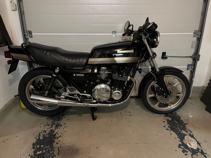
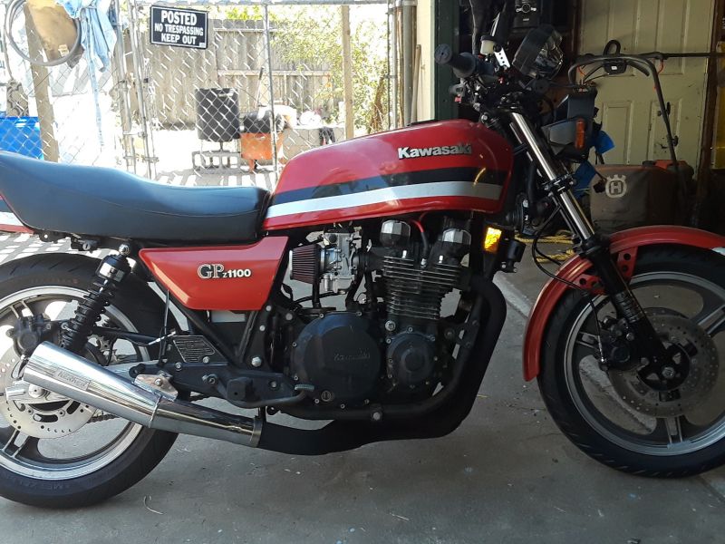
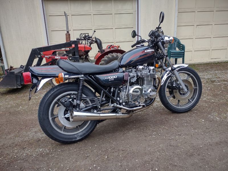
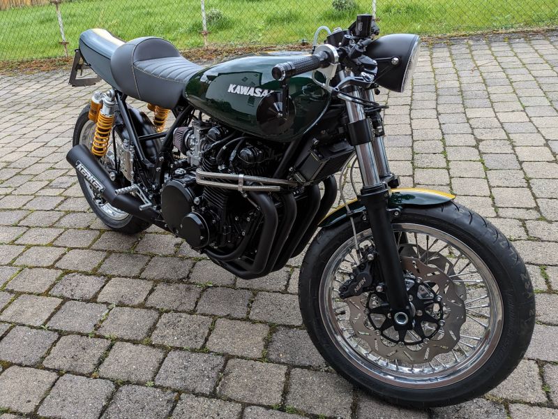
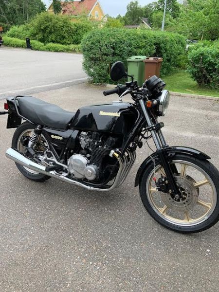
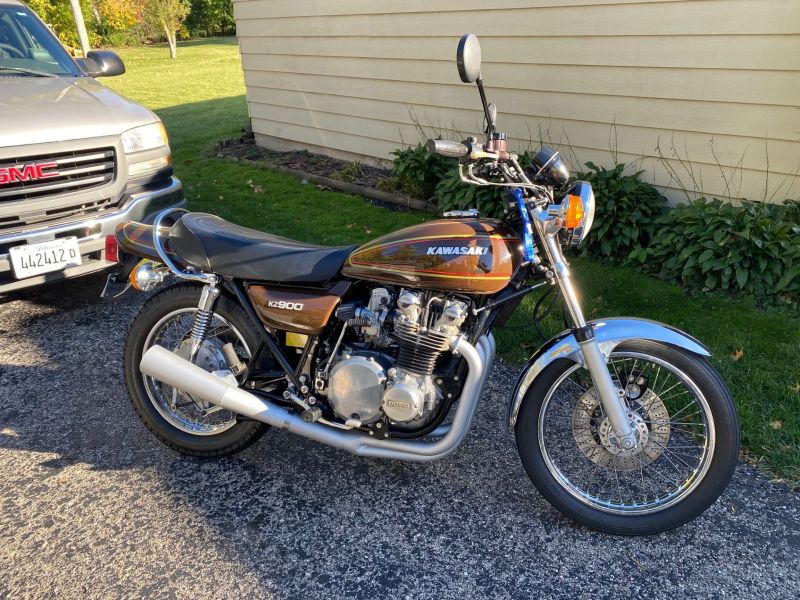
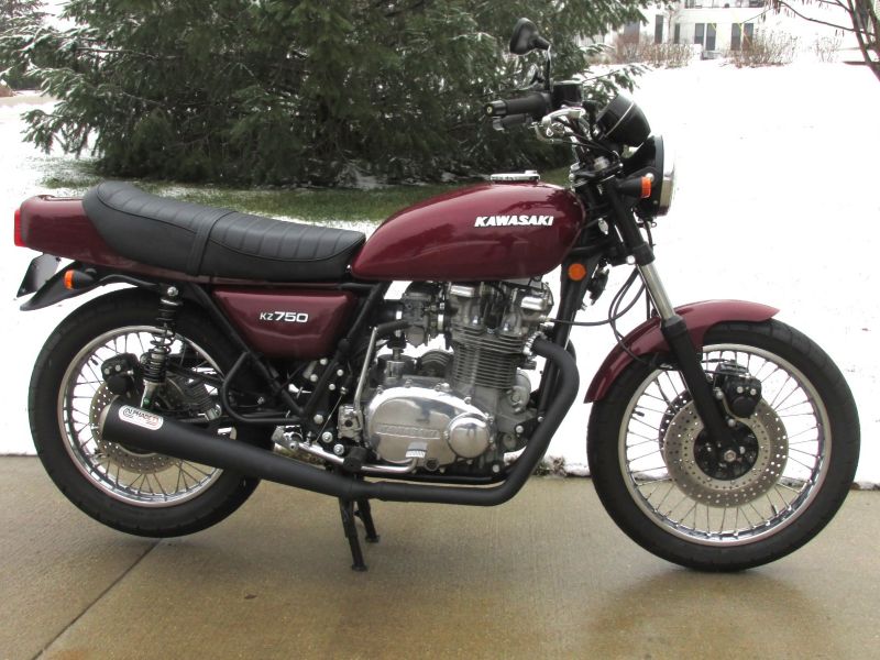
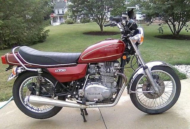
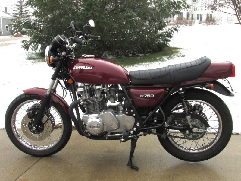
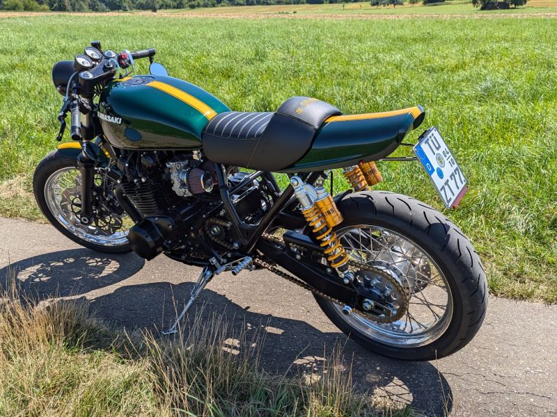
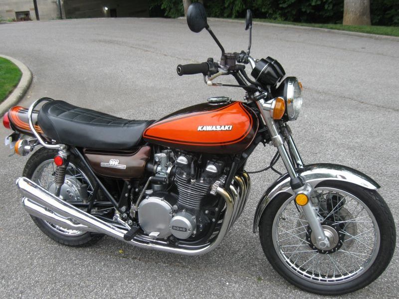
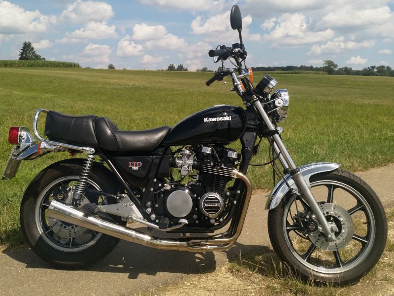
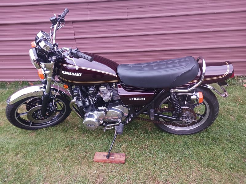
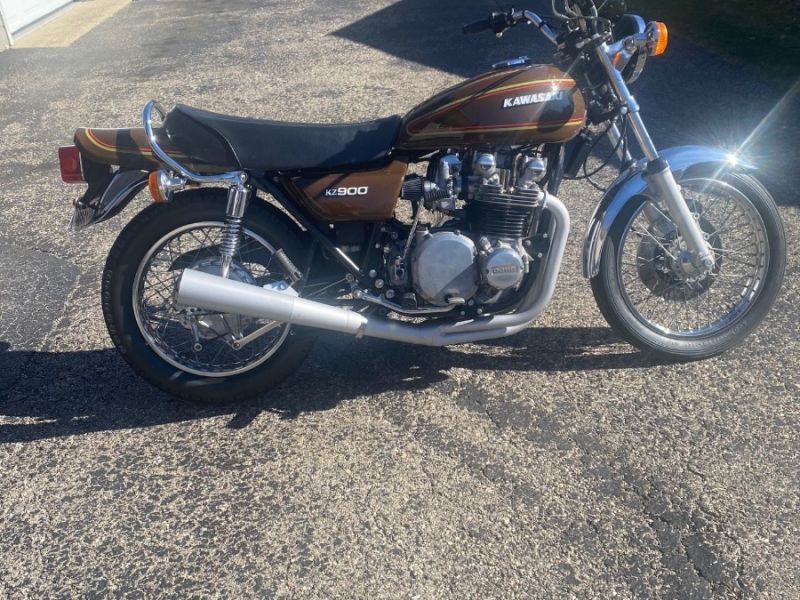
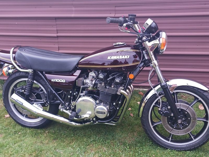
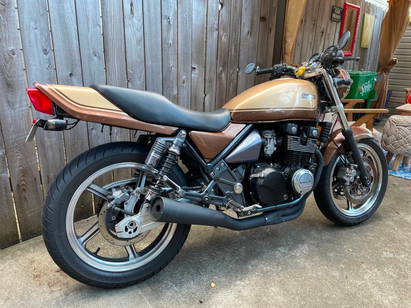
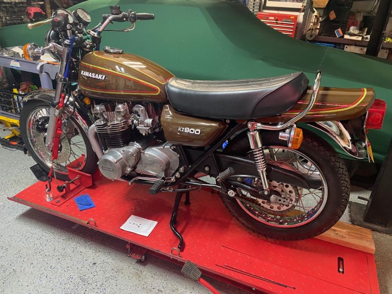
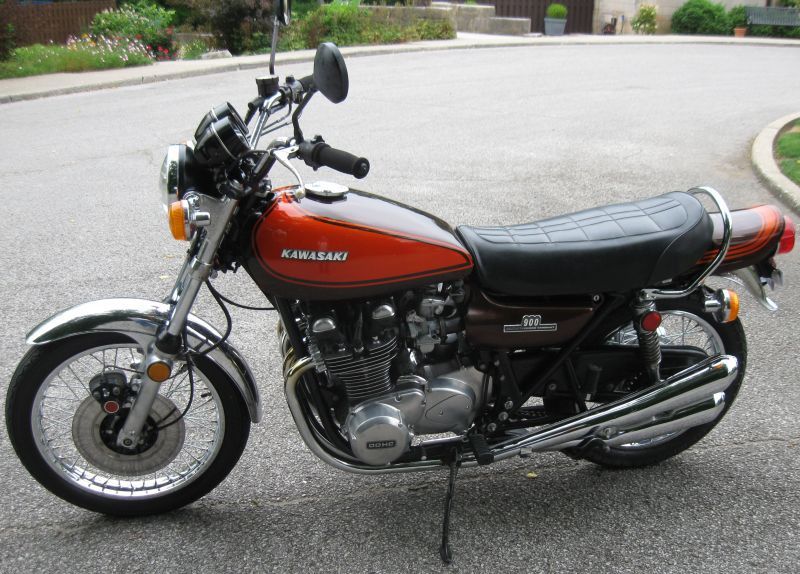
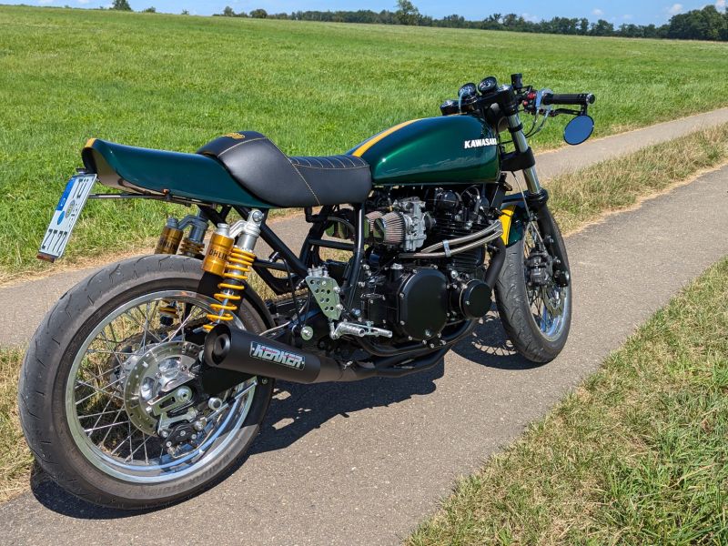
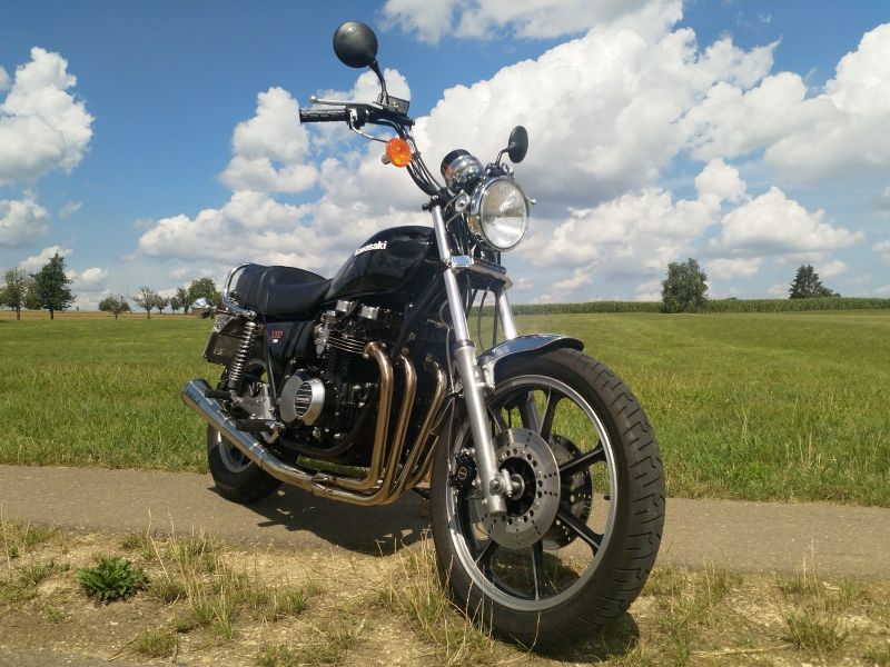
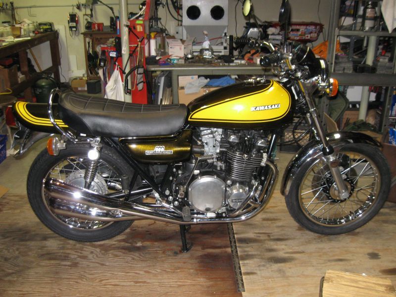
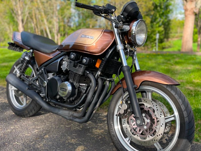
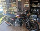
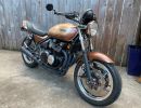
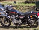
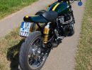
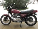
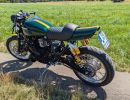
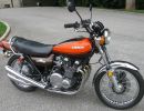
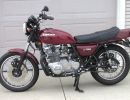
KZR's Bikes of the Month for 2024
why are there separate ground wires for some of the indicator lights?

More
20 Feb 2023 10:51 #880512 by katz
Hi,
I'd like to understand why some of the indicator lights have their own ground and don't use the common ground wire.
For example on my 1985 KW ZL900 both turn signals, high beam and head light fault indicators share the same ground wire (black/yellow), but neutral gear indicator and oil warning light have their own ground wire (brown). Coolant temperature warning light has similar setup. At some point I'd like to install a digital speedometer (with all the indicator lights built in) but the model I'm looking at has only one ground wire (black) for all indicator lights.
I'm not sure how to put those two sets of wires together. I'd like to understand the reason for those separate ground wires, can anyone explain?
Thanks,

Katz
 

Please Log in or Create an account to join the conversation.

More
20 Feb 2023 11:44 #880514 by Wookie58

Hi,
I'd like to understand why some of the indicator lights have their own ground and don't use the common ground wire.
For example on my 1985 KW ZL900 both turn signals, high beam and head light fault indicators share the same ground wire (black/yellow), but neutral gear indicator and oil warning light have their own ground wire (brown). Coolant temperature warning light has similar setup. Brown is ignition live on Kawasaki bikes -Neutral light, oil pressure light etc go to ground through the switches to the engine cases 
At some point I'd like to install a digital speedometer (with all the indicator lights built in) but the model I'm looking at has only one ground wire (black) for all indicator lights. Should work fine, as I said the indicator lights go to ground through the sensor wires and switches
I'm not sure how to put those two sets of wires together. I'd like to understand the reason for those separate ground wires, can anyone explain?
Thanks,

Katz

 
See Bold text above

Please Log in or Create an account to join the conversation.

  • SWest
  • Offline
  • Sustaining Member
  • 10 22 2014
More
20 Feb 2023 13:29 #880522 by SWest
I added a extra ground wire to the frame for the top box lights. Even though they all go to the same place it made a noticeable difference. Less load on the grounding circuit. 
Steve

Please Log in or Create an account to join the conversation.

  • Scirocco
  • Offline
  • Premium Member
  • Never change a running system
More
20 Feb 2023 13:41 #880523 by Scirocco
Neutral light and oil pressure light are connected (input) to ignition 12+ Volts (brown wire). The oil pressure switch and Neutral light switch close the electric circle to ground.

Please Log in or Create an account to join the conversation.

More
20 Feb 2023 13:42 - 20 Feb 2023 13:50 #880524 by katz
Hi,
Thanks for replying. "Brown is ignition live" - I think that means that circuit is closed when you turn the key and brown cable becomes the ground (gets connected to battery negative terminal)? So is this about the difference between "direct battery ground" and "battery ground controlled by ignition switch"?
I'd like to confirm because I have a third set of "signal/ground" wires, for coolant temperature warning (red/white and blue/red).
These connections are a little confusing because on the digital speedometer wiring diagram all indicator lights (turn signals, high beam, neutral gear, oil warning, etc.) have ground going through "switch key" (I'm guessing that's your "ignition live"), only "clock power" has a direct connection to the battery.

EDIT: I missed that part, "go to ground through the switches", the post from Scirocco helped. So brown wire is not the ground, it's the "signal" (or positive) wire?

Thanks a lot!
Last edit: 20 Feb 2023 13:50 by katz.
The following user(s) said Thank You: Wookie58

Please Log in or Create an account to join the conversation.

More
20 Feb 2023 14:52 #880527 by Wookie58
Can be a little confusing until you get your head around, the power supply is a constant ignition live and the ground is switched (so back to front from what you may be used to) oil pressure lights etc work this way on almost all vehicles (car and bike)
The following user(s) said Thank You: howardhb

Please Log in or Create an account to join the conversation.

More
21 Feb 2023 12:07 #880576 by katz
I'm glad you pointed that out, I had another look at the digital speedometer diagram and I noticed small + and - signs next to each indicator input.
Both turn signals, high beam and emergency lights have a + (plus) sign next to them while neutral gear and oil indicator have a - (minus) sign next to them.
I'll use a voltage meter to check if voltage shows up as negative for the neutral gear indicator, for example. I didn't realize some indicator wires were "reversed".
Thanks for all the help!

Katz

Please Log in or Create an account to join the conversation.

More
21 Feb 2023 12:30 - 21 Feb 2023 12:31 #880577 by Wookie58

I'm glad you pointed that out, I had another look at the digital speedometer diagram and I noticed small + and - signs next to each indicator input.
Both turn signals, high beam and emergency lights have a + (plus) sign next to them while neutral gear and oil indicator have a - (minus) sign next to them.
I'll use a voltage meter to check if voltage shows up as negative for the neutral gear indicator, for example. I didn't realize some indicator wires were "reversed".
Thanks for all the help!

Katz
It's not so much a case of reversed, at the end of the day you can put a switch anywhere in a circuit to cause a "make/break" action. By switching the oil/neutral etc on the ground side you reduce the amount of wiring (only one wire to each switch instead of two if you switch the positive) sometimes it's done for safety reasons (spiral contacts for car airbags are on the ground side so a short in the colum wiring won't trigger the airbag) horns are generally switched on the earth side as the near 0v (nominal electrical pressure) after the horn reduces the arcing at the switch contacts. You may find my electrical guide in the FAQ section useful
Last edit: 21 Feb 2023 12:31 by Wookie58.

Please Log in or Create an account to join the conversation.

  • Scirocco
  • Offline
  • Premium Member
  • Never change a running system
More
21 Feb 2023 13:09 - 21 Feb 2023 13:14 #880578 by Scirocco
Some switches/wires are located before the device (hot wire 12+Volts) and some after the device, to switch to battery negative terminal/ground/frame/engine case. In the end both variants close/open the electric circle or switch on/off the divice (Voltage/Current flow).
Last edit: 21 Feb 2023 13:14 by Scirocco.

Please Log in or Create an account to join the conversation.

More
22 Feb 2023 12:13 #880637 by katz
Yes I understand that circuit can be opened at any point, but I'm saying "reversed" because of the digital aspect of the speedometer I'm looking at. I don't think digital circuits take well to reversed polarity. I'm no expert but the manual for that digital speedometer talks about adding a diode to the circuit to prevent such issues. At any rate I think the speedometer wiring is actually matching the motorcycle wiring (in terms of + and - "direction", colors are all different).
Thank you both (Wookie58, Scirocco), I would have missed all those symbols if it wasn't for your posts.
Best,
Katz

Please Log in or Create an account to join the conversation.

More
22 Feb 2023 13:17 #880644 by Wookie58
No worries, if you are unsure post the wiring diagram for your bike and the new speedo you have and I will be able to advise you

Please Log in or Create an account to join the conversation.

Powered by Kunena Forum

If you like KZR Please consider making a donation. Thank you.

KZRider is free, but not without cost.

Please consider chipping in a few bucks to help cover the cost of running the KZR servers.