Welcome, Guest
Username: Password: Remember me

TOPIC:

Setting timing with points.... 07 Sep 2013 11:06 #605362

  • Old Man Rock
  • Old Man Rock's Avatar
  • Offline
  • User
  • Posts: 6224
  • Thank you received: 225
The bare bones diagram was intended for the ignition/charging system only... Leave (dis-connect) the head light and all other non ignition accessories out of circuit for now.

With the new ignition components, Dial in the points/dwell to spec.

Get to this point, get her running correctly with minimum/expected voltage drops (< 1.5Vdc) when running. Insure charging up to 13 - 13.5Vdc pending rpm and measure voltage drops as depicted in the lightning bolt diagram Patton provided.

If all good, then add accessory aka headlight one at a time, remeasuring for voltage drops as you add components into the circuit.
1976 KZ900-A4
MTC 1075cc.
Camshafts: Kawi GPZ-1100 .375 lift
Head: P&P via Larry Cavanaugh
ZX636 suspension
MIKUNI, RS-34'S...
Kerker 4-1, 1.5" comp baffle.
Dyna-S E.I.
Earls 10 row Oil Cooler
Acewell 2802 Series Speedo/Tach
Innovate LC1 Wideband 02 AFR meter

Phoenix, Az

Please Log in or Create an account to join the conversation.

Setting timing with points.... 07 Sep 2013 14:35 #605376

  • loudhvx
  • loudhvx's Avatar
  • Offline
  • KZr Legend
  • Posts: 10868
  • Thank you received: 1615
The original question has come up several times in the past, so I thought I'd post it again in case someone searches this. I didn't read all the responses, so maybe you already figured it out.
EDIT: It appears you figured it out. Nice job. B)

On an inline-4, if you use resistance checks across the points to determine if they are open or closed, you have to put a piece of paper in the other set of points. If you don't, then you will go from 0 ohms to about 8 to 10 ohms when the points open.

Putting a piece of paper in the other set of points should make the ohms swing from 0 to infinite.
Another option, which produces the same result, is to disconnect the wires on the coil primaries.

Without making the above changes, the resistance only changes to about 8~10 ohms. This is because the two coils are wired to the same power source, they are connected together at their primaries, and they are in parallel. So when you measure the resistance on one open set of points, you are measuring the resistance of the coil in the circuit you are testing, plus the resistance of the coil in the other ignition circuit.

If you use a voltage test, you don't have to make any changes... leave everything connected, and don't need paper on the other points. But this can drain the battery or heat up the coils.
The following user(s) said Thank You: 74ullc

Please Log in or Create an account to join the conversation.

Last edit: by loudhvx.

Setting timing with points.... 07 Sep 2013 16:41 #605395

  • 74ullc
  • 74ullc's Avatar Topic Author
  • Offline
  • User
  • Posts: 325
  • Thank you received: 23
I've found some very interesting wiring done by the PO. Imagine that huh. He put one of these aftermarket right side control switches on the bike. Told me he did when I bought it, first thing I asked was if he had the original, he said he threw it away. :(


www.z1enterprises.com/ItemDetails.aspx?i...Z900&item=EM99-68892

During voltage drop testing I found a connection getting too hot to touch. The connection at the brown (power) wire from the harness going into the switch is getting hot hot hot! The wiring on this aftermarket switch is different than the original for my bike. So the single brown power wire from the harness splices into two wires going into the new switchblock. This connection, the two to one, is getting very hot.

The problem appears to be the way he connected the new control switch to the bike harness. He cut the original handlebar switchblock wires about 6 inches up from the OEM bullet connections, then cut the ends off the aftermarket switchblock wires, then used some cheesy butt connectors to connect those together. The good thing is that he didn't cut the original harness. Bad thing is he did a poor job on the connections.

When I took the tape off this mess two of the wires fell out of the connectors they are so loose.

I'm going to buy some good butt connectors and use those to connect the switch wires properly. The auto parts store has some that have shrink tubing built on, I believe even some sort of low temp solder is in there. Something in there melts when you put a heat gun on the tubing locking that wire in there good. I've used them on other things, with very good results.

The left side switch is wired in the same way even though it is an OEM Kawasaki switch. I don't think its the OEM switch to my bike, no hazard button and appears to be an external handlebar wiring switch. Not internal like the LTD was.

If anyone has a rebuild-able set of original 1977 KZ1000 LTD switches I'm interested. B)
Gulf Coast, Texas
1977 KZ1000LTD
1984 VF700F

Please Log in or Create an account to join the conversation.

Setting timing with points.... 07 Sep 2013 18:15 #605406

  • Motor Head
  • Motor Head's Avatar
  • Offline
  • User
  • FIX UP YOUR BIKE RIGHT AND CHEAP
  • Posts: 5138
  • Thank you received: 391
That heat is resistance. Doubt it should have two wires into one at the switch. Follow your wiring diagram to see which wires were connected, and which were contacted inside the OEM switch when turned on. The PO has Fubarded it. Make it right and you will get rid of at least that electrical problem. The T-up stuff won't go to waste either. Clean and lube the advancer properly, lube the wear blocks on the points sets, get it all gaped and timed correctly, and the bike will more than likely run well.
1982 KZ1000LTD K2 Vance & Hines 4-1 ACCEL COILS Added Vetter fairing & Bags. FOX Racing rear Shocks, Braced Swing-arm, Fork Brace, Progressive Fork Springs RT Gold Emulators, APE Valve Springs, 1166 Big Bore kit, RS34's, GPZ cams.
1980 KZ550LTD C1 Stock SOLD Miss it
1979 MAZDA RX7 in the works, 13B...

Please Log in or Create an account to join the conversation.

Setting timing with points.... 07 Sep 2013 19:34 #605414

  • 74ullc
  • 74ullc's Avatar Topic Author
  • Offline
  • User
  • Posts: 325
  • Thank you received: 23
Looks like the PO did manage to get all the wires connected to the correct wires. The reason for the single brown from harness to the two wires into the switch is the differences in the two switches. In the original that brown wire did the job of three wires that the new switch uses.

Original switch.....brown goes into switch and powers headlight switch and engine stop switch. When engine stop switch is put in RUN position it then powers the red/yellow wire to the coils and also the starter button. Then when the started button is pushed it sends the power out thru the black wire, thru the clutch switch.

This new switch needs two power wires going into it. One for the headlight side and one for the engine stop switch side. Then when the stop switch is put into RUN position it powers the red/yellow wire but not the starter button. To get power to the starter button you have to grab it from the red/yellow wire to the coils. There is a black wire and a red/white wire out of the starter button. You have to tie the red/yellow coil wire and the red/white wire together, that way when the engine stop switch is in RUN position you get power to the starter button.

One cool thing this switch will allow is to turn on the running lights without the headlight on too. I guess thats cool anyways. I'm going to wire it up that way.

I was kinda hoping to find that the single to double connector was a mistake and causing all that voltage drop. It's not a mistake but I think it is causing voltage drop thru that bad connection the PO made. There is an unused brown power wire in the harness. It shows it on the wiring diagram and I found it on my bike. I'm going to use that extra power wire to power one of the switch power wires and use the original to power the other. That way at least those will be single to single wire connections. I'll then see if that helps the voltage drop.

Looking at the wiring diagram it seems like that single brown wire powers too many things on this bike.
Gulf Coast, Texas
1977 KZ1000LTD
1984 VF700F

Please Log in or Create an account to join the conversation.

Setting timing with points.... 07 Sep 2013 19:40 #605416

  • Motor Head
  • Motor Head's Avatar
  • Offline
  • User
  • FIX UP YOUR BIKE RIGHT AND CHEAP
  • Posts: 5138
  • Thank you received: 391
Where does the second brown wire come from in the harness side that you found? It must still be a Switched power source, after the ignition is On I'd say. Make sure it is that way, also that the wire comes from the correct fuse in your fuse panel.
If the PO had both the headlight and Ignition off of 1 brown wire, which would be 14 gauge or maybe smaller. That would be to small to handle the load of each. Once you hook this up so each has its own power feed that should cure or limit that voltage drop.
1982 KZ1000LTD K2 Vance & Hines 4-1 ACCEL COILS Added Vetter fairing & Bags. FOX Racing rear Shocks, Braced Swing-arm, Fork Brace, Progressive Fork Springs RT Gold Emulators, APE Valve Springs, 1166 Big Bore kit, RS34's, GPZ cams.
1980 KZ550LTD C1 Stock SOLD Miss it
1979 MAZDA RX7 in the works, 13B...

Please Log in or Create an account to join the conversation.

Setting timing with points.... 07 Sep 2013 20:13 #605421

  • 74ullc
  • 74ullc's Avatar Topic Author
  • Offline
  • User
  • Posts: 325
  • Thank you received: 23
The brown wire comes out of the ignition switch. The brown wire is fed from the white wire going into the switch. White wire goes thru the 20AMP fuse and then to the ignition switch. A single brown wire comes out of the ignition switch and then according to the wiring diagram splits off in a few different places to power different things. One of the ends of this brown wire is left empty. Thats the one I saw in the manual and then found on the bike. But yes, they all originate from that single brown wire out of the ignition switch.

It powers the headlight, ignition, turn signal relay, brake light switch....maybe a few other things.

BUT I still have some digging to do. Because, the brown wire in the headlight bucket, right out of the ignition switch, is thicker than the wire that emerges from the harness going to the right side switchblock. I'm guessing the wire going to the switchblock is only 18ga, its thin.

The first foot or so of harness out of the headlight bucket has the original black encasing on it. But then right over the intake cam it turns into electric tape. Its out of this electric tape wrapped part that the brown wire powering my switchblock comes from.

I'm going to unwrap every inch of this wiring and find out exactly whats going on it there. The reward wrapped section looks to have been done much longer ago than the wrap on the switchblock sections. So I think this will be at least two owners ago in there. The PO I bought it from only had it three months.

BTW....do you know what a factory connection where a few wires come together look like? In the wiring diagram it shows these connections as a heavy dot over where the lines cross.
Gulf Coast, Texas
1977 KZ1000LTD
1984 VF700F

Please Log in or Create an account to join the conversation.

Setting timing with points.... 07 Sep 2013 20:19 #605423

  • Motor Head
  • Motor Head's Avatar
  • Offline
  • User
  • FIX UP YOUR BIKE RIGHT AND CHEAP
  • Posts: 5138
  • Thank you received: 391
The factory does a "Splice". Usually a connection, like a crimped metal connection non insulated and many times not soldered. These can become corroded, wires can be partially broken on some strands.

I see on your diagram the single brown that you found in the head light bucket. This looks like it would be for an accessory. I also see where the White comes in from the main fuse to the ignition Switch, then connects to the brown for several circuits. It would have worked when the bike was new of course. But after all these years and PO's messing around, it is probably in need of some work. Later they changed the switch and circuits, adding more fuses etc. You may want to consider doing an upgrade to the system, put in an ATO style blade Fuse box, and rewire the bike. Once done you will have way less problems.
If you had such a voltage drop and spent money on the Dyna S, you would surely burn it out with that voltage issue.
1982 KZ1000LTD K2 Vance & Hines 4-1 ACCEL COILS Added Vetter fairing & Bags. FOX Racing rear Shocks, Braced Swing-arm, Fork Brace, Progressive Fork Springs RT Gold Emulators, APE Valve Springs, 1166 Big Bore kit, RS34's, GPZ cams.
1980 KZ550LTD C1 Stock SOLD Miss it
1979 MAZDA RX7 in the works, 13B...
The following user(s) said Thank You: 74ullc

Please Log in or Create an account to join the conversation.

Last edit: by Motor Head.

Setting timing with points.... 07 Sep 2013 21:43 #605437

  • 74ullc
  • 74ullc's Avatar Topic Author
  • Offline
  • User
  • Posts: 325
  • Thank you received: 23
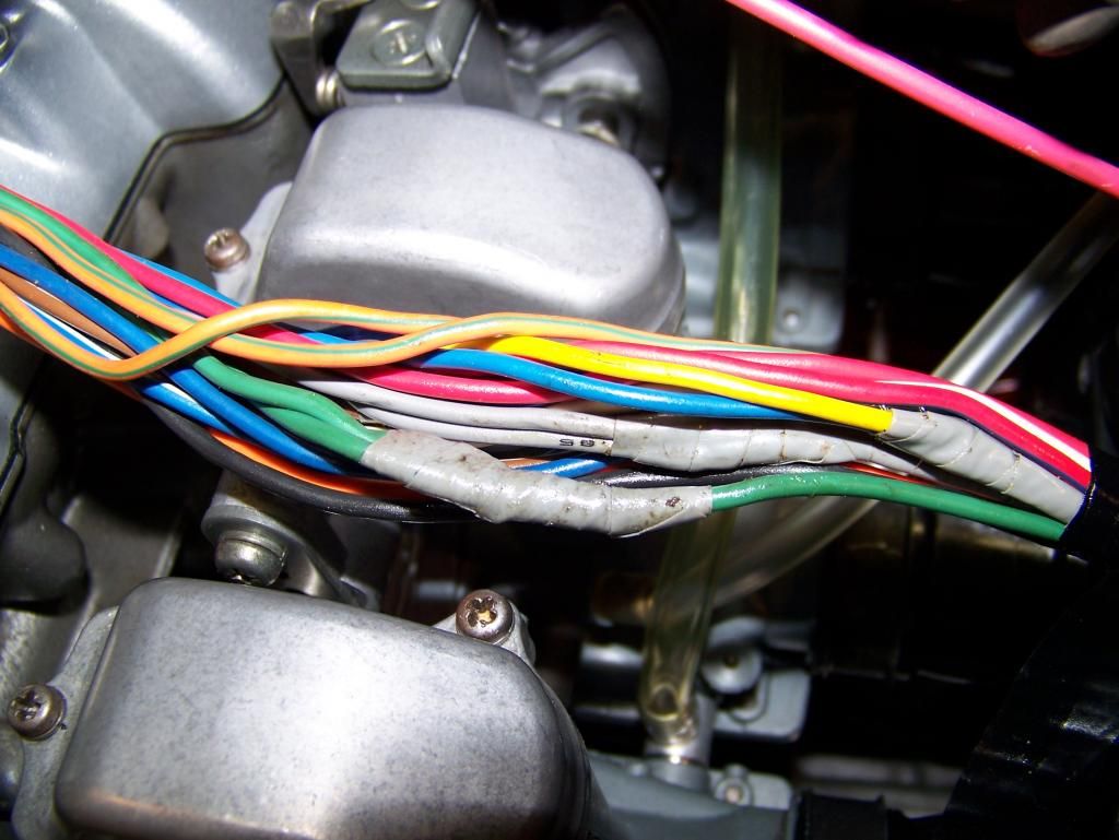
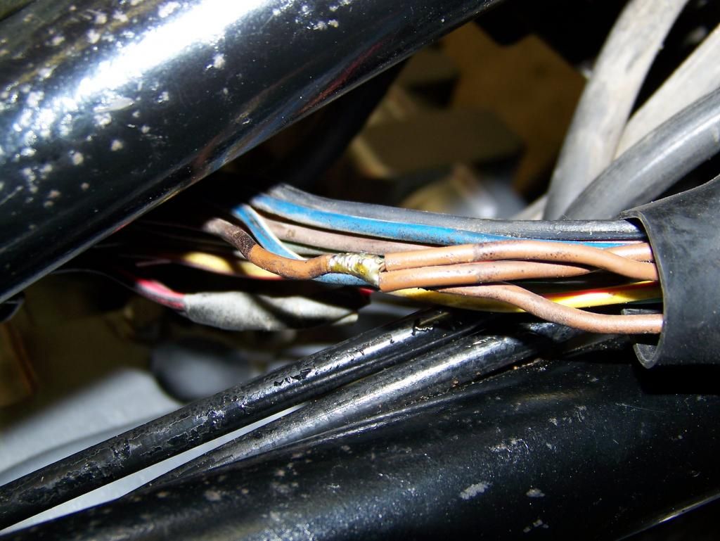
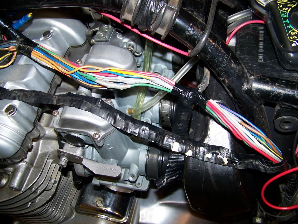
I think these are original factory splices. I unwrapped one to take a look and its a very professional looking solder joint.


One that was already unwrapped, this is a 1 to 3 brown wire splice, 1 goes to the horn, 1 goes to the right switchblock and one goes to the dead end.


Did the factory wrap the harness with this ribbon looking stuff? The stuff draped across the top of the carb. Sure is clean under there.

Gulf Coast, Texas
1977 KZ1000LTD
1984 VF700F

Please Log in or Create an account to join the conversation.

Last edit: by 74ullc.

Setting timing with points.... 07 Sep 2013 23:55 #605460

  • 74ullc
  • 74ullc's Avatar Topic Author
  • Offline
  • User
  • Posts: 325
  • Thank you received: 23
I unwrapped it all the way to the six pin connectors and fuse box. The rest of the harness looks pristine. No more funny stuff, only the splices like in the pic I posted. All wrapped the same way with that grey tape. Thats why I think those splices are possibly factory, either that or someone knew what they were doing.

I wrapped the harness back up using the same ribbon type stuff that was on it. Worked great.

So back to the handlebar switchblocks. I'll get the new bullet connectors installed, getting rid of the PO's really bad butt splices and see how it does.

Anyone see any problems with using the hazard circuit (green/orange) to power my headlight? With this aftermarket switchblock I can power the ignition with one circuit and the headlight with another.

The hazard circuit on my bike is unused and is powered thru the ignition switch with the same white wire as the brown circuit that goes thru the 20AMP fuse.

Should greatly reduce the load on that brown wire!
Gulf Coast, Texas
1977 KZ1000LTD
1984 VF700F

Please Log in or Create an account to join the conversation.

Setting timing with points.... 10 Sep 2013 15:38 #605857

  • bemoore
  • bemoore's Avatar
  • Offline
  • User
  • Posts: 190
  • Thank you received: 4
Re: Voltage Drops

I had a similar voltage drop from the battery to my coils. On here somewhere is a writeup about a "coil relay mod". It details how to run power from your battery through a relay to the coils. I did this, and the voltage drop to the coils went from 3 or 4 volts (I don't remember exactly) to a few tenths of a volt. I also had a problem similar to your "full throttle at high rpms only" problem, except mine was worse. Mine wouldn't rev past about 4000 rpms. This mod helped that problem a lot. It's not perfect now, but I can rev to redline. I think I still need a jetting change, though.

Also, another mod I did that I think may be better (at least in bang for the buck), was replacing the fuse box. At the time, I was going through the whole bike and cleaning up all the electrical connections. I still had too much voltage drop through my fuse box, even after cleaning every contact and fuse. I replaced it with a $3 blade type fuse box from a discount parts store. The difference was amazing. My lights were brighter, my blinkers were brighter and faster, and my horn was louder. I wish I'd have done this mod first. I might not have needed the coil relay mod.

If you do the coil relay mod, be sure to put a fuse inline with the wire connected to the + terminal of the battery.
77 KZ650C1 w/Kerker 4-1

Please Log in or Create an account to join the conversation.

Setting timing with points.... 10 Sep 2013 22:19 #605919

  • Motor Head
  • Motor Head's Avatar
  • Offline
  • User
  • FIX UP YOUR BIKE RIGHT AND CHEAP
  • Posts: 5138
  • Thank you received: 391
Those splices look factory to me. I think that one of the reasons the Coil Mod was popular on some of these old bikes is this Brown Wire Splice. Feeding that splice, with just one of the same gauge wire is a bad choice. I know Kawasaki made it like that, but that was one of there mistakes. Latter they of course changed those circuits, added more fuses etc. There is a lot of stuff produced that has been miss-engineered from the factory.
Personally i'd go with a New ATO type Panel and rewire that bike to make sure of the correct current flow.
OMR (Old Man Rock) has a good write up on it, and his is a similar year/ model. Member Loudhvx has great bare bones wiring diagrams, in his signature, Bare Bones for Matty Light thread. Not to difficult to do, and you will have a much better electrical system. No more dull head light, much better spark etc.
1982 KZ1000LTD K2 Vance & Hines 4-1 ACCEL COILS Added Vetter fairing & Bags. FOX Racing rear Shocks, Braced Swing-arm, Fork Brace, Progressive Fork Springs RT Gold Emulators, APE Valve Springs, 1166 Big Bore kit, RS34's, GPZ cams.
1980 KZ550LTD C1 Stock SOLD Miss it
1979 MAZDA RX7 in the works, 13B...

Please Log in or Create an account to join the conversation.

Powered by Kunena Forum