
LED Lighting on an Early-80's Kawi
- gavroyer
-
 Topic Author
- Offline
- User
-

Registered
- Posts: 101
- Thanks: 15
LED Lighting on an Early-80's Kawi
29 May 2019 15:18 - 29 May 2019 15:38
I know a lot of people want to use LED lighting on their older bikes. LEDs are brighter, last longer, draw less current, and in general can allow for a healthier charging system. However, the problem of load remains. There's a lot of stuff on these old bikes that depends on a certain amount of current being drawn through the circuit in order to work. LED turn signals that don't flash (or flash too quickly), brake warning lights on the dashboard, etc. All of these components expect a certain amount of power to flow through the circuit in order to operate. That's just how they did it in the 80s.
The good news is that in today's modern world, we have the technology to make things work. More vehicles than ever are now using low-power LED lighting and it's easier than ever to upgrade your bike with better lighting. I'll talk about the theory behind how some of the circuits in these bikes work and how to make them new with upgraded lights and still keep all of the functionality working.
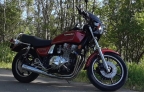
I'm basing all of these explanations on my 1980 KZ440A1, but similar principles should apply to most of these older bikes, since from all of the ones I've seen, they work mostly similarly.
PART 1: Turn Signals.
One of the easier things to make work are turn signals. In their original form, the turn signals have a switched supply (the turn signal switch in the control pod) which then flows to the turn signals. The turn signal switch is a simple SP3T switch (Single pole, triple throw) switch with the central throw simply not connected. One outer throw turns on the left signal, and the other the right. Power flows into the switch from the flasher unit (usually under one of the side covers) which intermittently delivers power in a regular, pulsing flow.
To recap, when you switch the left (or right) turn signal on, electricity flows out of the battery (through the switched 12v wire from the ignition), into the flasher, then pulses flow from the flasher, into the now-on switch, then out to the correct bulbs (the front and rear signal bulbs, plus the dash indicator). The electricity then returns to the negative of the battery through the ground system (either the frame or a ground wire). I've included a schematic diagram of this circuit below:

The problem component we typically ends up being the flasher. The older style flashers are of the thermal type, which use a small resistive heating element and a bimetallic strip. When the switch is turned on, current flows into the resistive heater. The resistance of the heating element limits the current that flows through the circuit, meaning the lights don't have enough power to light up, so they stay off. As the heater warms, the bimetallic strip curves, and when it curves all the way, it completes a short circuit around the heater, bypassing it, and allowing the full battery voltage to light up the light bulbs. When this happens, very little current flows through the heater (because the current through a circuit is inversely proportional to its resistance), so the heating element cools down. This causes the bimetallic strip to curve again, and eventually it stops making contact, ceasing the short circuit, turning off the lamps, and turning the heater back on. This cycle repeats until you turn off the turn signal.
This has a nice side effect in that if one of the lamps burns out, the current through the flasher unit is reduced, which means the bimetallic strip cools faster and snaps back to open faster. The effect is that the pulses speed up, i.e. the lights flash faster, indicating a burned out lamp. However, LEDs also draw much less current than lamps, which means they act like the bulb is burned out too. They draw so little current, that --depending on the flasher-- the flasher may not even operate, or may get stuck in the on position. You can mitigate this by placing a resistor in line with the flasher, but this will cause extra power draw, negating one of the primary benefits of having LEDs in the first place.
LED-compatible flashers solve this problem using transistors and solid state electronics to control the rate of flashing. And it just so happens that they can be found very cheaply. I found one of these at my local parts store, but the same unit is available on Amazon for about half what I paid too. Regardless, you want to get an "EP35" flasher, and ensure that it has three terminals and has "LED" written on it. That indicates an LED-compatible flasher.
Now we have a problem. The original flasher on most of these has two terminals, but this flasher has three? We need a bit of additional wiring in order to make this work. Transistorized flashers require their own ground to work, so we'll need to add a ground wire to the bike that we can attach to the flasher. Going forward, I'll assume you're using an EP35 flasher. There are three terminals, numbered 31, 49, and 49a:
Pick a bolt (I used one of the battery tray bolts on my 440), remove it, and thread
For the electrically inclined among you, I've drawn up a revised schematic here:

Now when you turn on your turn signals, the lights will flash at a normal rate, and everything should work well.
The good news is that in today's modern world, we have the technology to make things work. More vehicles than ever are now using low-power LED lighting and it's easier than ever to upgrade your bike with better lighting. I'll talk about the theory behind how some of the circuits in these bikes work and how to make them new with upgraded lights and still keep all of the functionality working.
I'm basing all of these explanations on my 1980 KZ440A1, but similar principles should apply to most of these older bikes, since from all of the ones I've seen, they work mostly similarly.
PART 1: Turn Signals.
One of the easier things to make work are turn signals. In their original form, the turn signals have a switched supply (the turn signal switch in the control pod) which then flows to the turn signals. The turn signal switch is a simple SP3T switch (Single pole, triple throw) switch with the central throw simply not connected. One outer throw turns on the left signal, and the other the right. Power flows into the switch from the flasher unit (usually under one of the side covers) which intermittently delivers power in a regular, pulsing flow.
To recap, when you switch the left (or right) turn signal on, electricity flows out of the battery (through the switched 12v wire from the ignition), into the flasher, then pulses flow from the flasher, into the now-on switch, then out to the correct bulbs (the front and rear signal bulbs, plus the dash indicator). The electricity then returns to the negative of the battery through the ground system (either the frame or a ground wire). I've included a schematic diagram of this circuit below:
The problem component we typically ends up being the flasher. The older style flashers are of the thermal type, which use a small resistive heating element and a bimetallic strip. When the switch is turned on, current flows into the resistive heater. The resistance of the heating element limits the current that flows through the circuit, meaning the lights don't have enough power to light up, so they stay off. As the heater warms, the bimetallic strip curves, and when it curves all the way, it completes a short circuit around the heater, bypassing it, and allowing the full battery voltage to light up the light bulbs. When this happens, very little current flows through the heater (because the current through a circuit is inversely proportional to its resistance), so the heating element cools down. This causes the bimetallic strip to curve again, and eventually it stops making contact, ceasing the short circuit, turning off the lamps, and turning the heater back on. This cycle repeats until you turn off the turn signal.
This has a nice side effect in that if one of the lamps burns out, the current through the flasher unit is reduced, which means the bimetallic strip cools faster and snaps back to open faster. The effect is that the pulses speed up, i.e. the lights flash faster, indicating a burned out lamp. However, LEDs also draw much less current than lamps, which means they act like the bulb is burned out too. They draw so little current, that --depending on the flasher-- the flasher may not even operate, or may get stuck in the on position. You can mitigate this by placing a resistor in line with the flasher, but this will cause extra power draw, negating one of the primary benefits of having LEDs in the first place.
LED-compatible flashers solve this problem using transistors and solid state electronics to control the rate of flashing. And it just so happens that they can be found very cheaply. I found one of these at my local parts store, but the same unit is available on Amazon for about half what I paid too. Regardless, you want to get an "EP35" flasher, and ensure that it has three terminals and has "LED" written on it. That indicates an LED-compatible flasher.
Now we have a problem. The original flasher on most of these has two terminals, but this flasher has three? We need a bit of additional wiring in order to make this work. Transistorized flashers require their own ground to work, so we'll need to add a ground wire to the bike that we can attach to the flasher. Going forward, I'll assume you're using an EP35 flasher. There are three terminals, numbered 31, 49, and 49a:
- 31 - Negative (Ground)
- 49 - Positive
- 49a - Lamp
Pick a bolt (I used one of the battery tray bolts on my 440), remove it, and thread
- Pick a convenient bolt near the flasher and remove it. I used one of the battery tray bolts on my 440.
- Create a ground wire with a female spade terminal on one end and a ring terminal on the other end. The ring terminal must fit around the bolt, and the spade terminal must fit onto the terminals on the flasher.
- Thread the ring terminal onto the bolt and tighten it down. Use a multimeter to ensure continuity (low resistance) between the negative battery post and the spade end of the wire.
- Attach the switched 12V wire from the bike to terminal 49 on the flasher, and the other turn signal connection to 49a. On my 440, the switched wire was brown and the other wire was orange.
- Attach the spade terminal of the ground wire to terminal 31 on the flasher. Fit the flasher into the rubber boot your original was in, and mount it to the bike.
For the electrically inclined among you, I've drawn up a revised schematic here:
Now when you turn on your turn signals, the lights will flash at a normal rate, and everything should work well.
1980 KZ440-A1 LTD
Attachments:
Last edit: 29 May 2019 15:38 by gavroyer.
The following user(s) said Thank You: martin_csr, linuxrob, Adrian719
Please Log in or Create an account to join the conversation.
- daveo
-
- Offline
- Premium Member
-

Registered
- Posts: 2983
- Thanks: 775
Re: LED Lighting on an Early-80's Kawi
29 May 2019 16:17 - 30 May 2019 07:28
Immediately after installing a Genuine LED Truck Lite 27270C headlight on my KZ1100A2, the two headlight-related indicator bulbs in my tach started to come on at low engine rpms, and turn off as rpms increased.
Knowing this would drive me nuts after five minutes, I chose to remove the offending bulbs from the tach and forget about it. Since then everything seems to work fine, but I need to monitor the headlight beam by checking the control switch.
Is this a common problem when installing these headlights, and is there a simple fix? I would rather have the indicator bulbs in and the lighting system operating properly.
1982 KZ1100-A2
Last edit: 30 May 2019 07:28 by daveo.
Please Log in or Create an account to join the conversation.
- gavroyer
-
Topic Author
- Offline
- User
-
Registered
- Posts: 101
- Thanks: 15
Re: LED Lighting on an Early-80's Kawi
30 May 2019 13:40
PART 2: Stop Lamp Indicator
Many late 70s and early 80's Kawasaki bikes had a stop lamp indicator on the dashboard somewhere (on my 440, it's in the tach next to the Oil Pressure warning lamp). The function of this lamp was to alert the rider that there was a problem with the taillight. Either the lamp had burned out or the wiring was faulty, and in either case there was a chance the stop lamp on the back would not come on when the brake was applied.
Under normal operation, the lamp is off. When either brake is applied, it lights up steady and and remains lit until the brake is released. This lets the rider know that the brake light is on and that the indicator lamp in the dashboard is still good. When the stop lamp bulb breaks, the indicator lamp flashes intermittently when the brake is not applied, which alerts the rider that the lamp is not working.
The way this works is by exploiting a property of light bulb filaments that causes them to act like a low-resistance short under very low voltage. This allows low-voltage circuits to be complete, but does so without heating up the lamp filament, thus causing it to glow. The lamp failure indicator switch sends this low-voltage output through the lamp, and if it encounters large resistance, it knows the lamp is broken.
LEDs (like regular diodes) are somewhat opposite to lamps in this regard. Under very low voltage, they act like an open circuit, blocking the flow of electricity until the voltage reaches a minimum cutoff, after which they act like a short (and light up). This means that the failure indicator thinks the filament is blown and indicates a lamp failure.
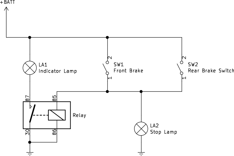
I've added a schematic of the stop lamp circuit below:

There are some easy ways to get the stop lamp indicator working. If you don't care about failures, the easiest is to use a standard normally-open (NO) Automotive relay to detect when the brakes are applied, and then switch the lamp circuit on. You need to use a relay for this because the indicator lamp has a switch ground (the switch is on the negative side of the lamp) whereas the brake lamp is a switched supply (the switches are on the positive side of the lamp). This causes the lamp to light up when the brakes are applied so that the rider knows the lamp is on and that the switches on the brake levers are working correctly. There is no lamp failure indication, so you'll need to turn around and look at the brake light to ensure that it lights up, but that's fairly simple.
To do this, you'll need a relay:
Because 86 and 30 are wired together, it doesn't matter which you connect the ground to; either will work. Then, attach the relay to your bike frame under the side cover near the brake failure plug, and plug the end in. Now you should have an indicator that lights up with the brake lights. Here's a schematic for this setup.
Another good way to do it would be to re-wire the indicator to be in series with the brake light. This will ensure that it still lights up correctly, but will remain dark if the brake is applied and the lamp doesn't light, thus providing failure indication as well (if you apply the brake and the light doesn't light, you know the brake light is out). You would need to find the wires for the indicator lamp behind the headlight, then unplug the wires from that and tape them off with electrical tape to prevent shorting.
Next, run some wires from the wires up front to the back of the bike where the brake light plugs in. Unplug the blue wire plug, then connect one end of your wire from the lamp in the front to one end of the blue wire, and connect the other end of the lamp wire to the other end. Try to match this schematic:
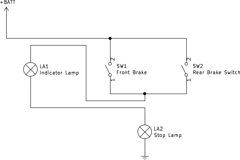
Ensure that the brake light still lights up (and is bright enough) and that the lamp in the dash comes on when you apply the brake. If everthing looks good, tape up the wires and ensure nothing will short, then you should be all set.
Many late 70s and early 80's Kawasaki bikes had a stop lamp indicator on the dashboard somewhere (on my 440, it's in the tach next to the Oil Pressure warning lamp). The function of this lamp was to alert the rider that there was a problem with the taillight. Either the lamp had burned out or the wiring was faulty, and in either case there was a chance the stop lamp on the back would not come on when the brake was applied.
Under normal operation, the lamp is off. When either brake is applied, it lights up steady and and remains lit until the brake is released. This lets the rider know that the brake light is on and that the indicator lamp in the dashboard is still good. When the stop lamp bulb breaks, the indicator lamp flashes intermittently when the brake is not applied, which alerts the rider that the lamp is not working.
The way this works is by exploiting a property of light bulb filaments that causes them to act like a low-resistance short under very low voltage. This allows low-voltage circuits to be complete, but does so without heating up the lamp filament, thus causing it to glow. The lamp failure indicator switch sends this low-voltage output through the lamp, and if it encounters large resistance, it knows the lamp is broken.
LEDs (like regular diodes) are somewhat opposite to lamps in this regard. Under very low voltage, they act like an open circuit, blocking the flow of electricity until the voltage reaches a minimum cutoff, after which they act like a short (and light up). This means that the failure indicator thinks the filament is blown and indicates a lamp failure.
I've added a schematic of the stop lamp circuit below:
There are some easy ways to get the stop lamp indicator working. If you don't care about failures, the easiest is to use a standard normally-open (NO) Automotive relay to detect when the brakes are applied, and then switch the lamp circuit on. You need to use a relay for this because the indicator lamp has a switch ground (the switch is on the negative side of the lamp) whereas the brake lamp is a switched supply (the switches are on the positive side of the lamp). This causes the lamp to light up when the brakes are applied so that the rider knows the lamp is on and that the switches on the brake levers are working correctly. There is no lamp failure indication, so you'll need to turn around and look at the brake light to ensure that it lights up, but that's fairly simple.
To do this, you'll need a relay:
- Solder a wire between pins 30 and 86 on the relay.
- Snip off the standard brake failure indicator from the wires as close to the box as you can.
- Attach spade terminals to the three wires left from the brake failure plug.
- Attach the brake-light-supply wire (blue on my 440) to terminal 85 on the relay.
- Attach the indicator lamp wire (green-white on my 440) to terminal 87 on the relay.
- Attach the ground wire (black-yellow) to pin 86 or 30 (whichever is easier).
Because 86 and 30 are wired together, it doesn't matter which you connect the ground to; either will work. Then, attach the relay to your bike frame under the side cover near the brake failure plug, and plug the end in. Now you should have an indicator that lights up with the brake lights. Here's a schematic for this setup.
Another good way to do it would be to re-wire the indicator to be in series with the brake light. This will ensure that it still lights up correctly, but will remain dark if the brake is applied and the lamp doesn't light, thus providing failure indication as well (if you apply the brake and the light doesn't light, you know the brake light is out). You would need to find the wires for the indicator lamp behind the headlight, then unplug the wires from that and tape them off with electrical tape to prevent shorting.
Next, run some wires from the wires up front to the back of the bike where the brake light plugs in. Unplug the blue wire plug, then connect one end of your wire from the lamp in the front to one end of the blue wire, and connect the other end of the lamp wire to the other end. Try to match this schematic:
Ensure that the brake light still lights up (and is bright enough) and that the lamp in the dash comes on when you apply the brake. If everthing looks good, tape up the wires and ensure nothing will short, then you should be all set.
1980 KZ440-A1 LTD
Attachments:
The following user(s) said Thank You: martin_csr, Adrian719
Please Log in or Create an account to join the conversation.
- Scirocco
-
- Offline
- Premium Member
-
Registered
- Never change a running system
- Posts: 4420
- Thanks: 2269
Re: LED Lighting on an Early-80's Kawi
30 May 2019 14:26daveo wrote:
Immediately after installing a Genuine LED Truck Lite 27270C headlight on my KZ1100A2, the two headlight-related indicator bulbs in my tach started to come on at low engine rpms, and turn off as rpms increased.
LED´s are like diodes = Need the correct polarity, bulbs gives a shit on AC,DC or polarity. They will do the Job anyway.
The headlight-related indicator bulbs are in the same power circuit and have to replace with LED´s.
My 1975 Z 1 B 900 Project
www.kzrider.com/forum/11-projects/605133...ears-deep-sleep-mode
www.kzrider.com/forum/11-projects/605133...ears-deep-sleep-mode
The following user(s) said Thank You: daveo
Please Log in or Create an account to join the conversation.
- daveo
-
- Offline
- Premium Member
-
Registered
- Posts: 2983
- Thanks: 775
Re: LED Lighting on an Early-80's Kawi
30 May 2019 14:53
These are the removed bulbs. Are LED replacements available with the same physical size, and contact configuration?
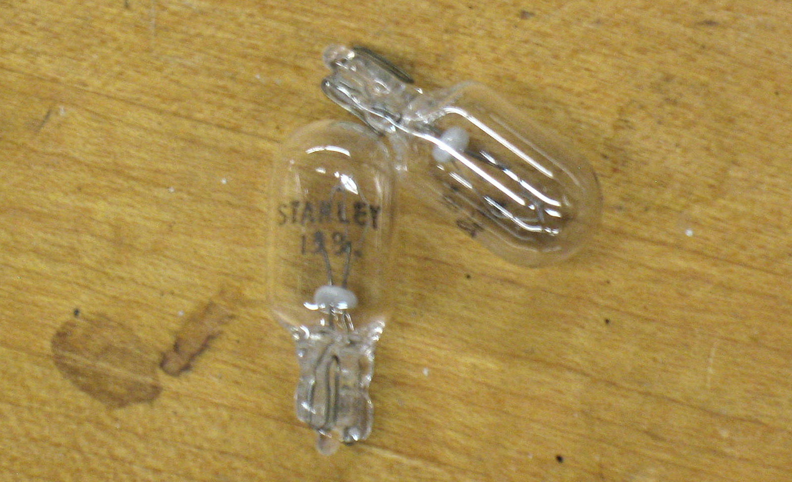
:whistle:
:whistle:
1982 KZ1100-A2
Attachments:
Please Log in or Create an account to join the conversation.
- SWest
-
- Offline
- Sustaining Member
-

Registered
- 10 22 2014
- Posts: 23588
- Thanks: 2957
Re: LED Lighting on an Early-80's Kawi
30 May 2019 15:04
YES
Z1b1000 1975 Z1b
kzrider.com/forum/11-projects/598262-kz-...-will-it-live#672882
kzrider.com/forum/2-engine/597654-poser?start=240#704229
kzrider.com/forum/11-projects/598262-kz-...-will-it-live#672882
kzrider.com/forum/2-engine/597654-poser?start=240#704229
Please Log in or Create an account to join the conversation.
- gavroyer
-
Topic Author
- Offline
- User
-
Registered
- Posts: 101
- Thanks: 15
Re: LED Lighting on an Early-80's Kawi
30 May 2019 17:49 - 30 May 2019 17:49
Failing that, you can likely get some diodes that would work to turn those into "LEDs" (not really, but they would only work one way). A diode in series with the lamp will effect reverse-polarity protection.
1980 KZ440-A1 LTD
Last edit: 30 May 2019 17:49 by gavroyer.
Please Log in or Create an account to join the conversation.
- loudhvx
-

- Offline
- KZr Legend
-

Registered
- Posts: 10864
- Thanks: 1621
Re: LED Lighting on an Early-80's Kawi
31 May 2019 09:36 - 31 May 2019 09:37
Thanks for the posts summarizing.
The brake flasher warning modification has already been done. I've posted it a couple times. With slightly different wiring.
www.kzrider.com/forum/4-electrical/61047...-s-to-1983-kz440-ltd
The brake flasher warning modification has already been done. I've posted it a couple times. With slightly different wiring.
www.kzrider.com/forum/4-electrical/61047...-s-to-1983-kz440-ltd
1981 KZ550 D1 gpz.
Kz550 valve train warning.
Other links.
Kz550 valve train warning.
Other links.
Last edit: 31 May 2019 09:37 by loudhvx.
Please Log in or Create an account to join the conversation.
- gavroyer
-
Topic Author
- Offline
- User
-
Registered
- Posts: 101
- Thanks: 15
Re: LED Lighting on an Early-80's Kawi
31 May 2019 09:42
I think the wiring is "the same", just with the relay backwards. Since relays are unpolarized components, it won't make any difference at all.
I actually did see your post Wednesday after I got my relay wired up. I'm going to keep thinking of a way to add dead-lamp detection to this circuit too.
I actually did see your post Wednesday after I got my relay wired up. I'm going to keep thinking of a way to add dead-lamp detection to this circuit too.
1980 KZ440-A1 LTD
Please Log in or Create an account to join the conversation.
Moderators: Street Fighter LTD