
De-twitching an electronic tachometer
- loudhvx
-

- Offline
- KZr Legend
-

Registered
- Posts: 10863
- Thanks: 1622
Re: De-twitching an electronic tachometer
02 Mar 2018 19:49 - 02 Mar 2018 19:55
The alternator signal dropping to ground means the tach will not be able to count revs reliably regardless of impedance because pulses will be missing randomly.
The 555 circuit shown simply does not work as drawn for the dyna s for the reasons explained. With a long dwell ignition like the dyna s, the 555's output just stays low.
Even with the reset wired conventionally, the output will not be as claimed due to the extended low input. The dwell is not 10% on the dyna s, it is over 80%. The dwell is over 300 deg, leaving less than 60 deg for the rest period. 300/360 is 83%. This means the primary signal is low most of the time, so it is not useful as a debounce input signal. It will force the output to look like the input, thus defeating the purpose of the debounce circuit.
I tested it. And I've used debounce circuits many times for other things, and have designed mods to make them work better. The standard textbook version is really only for learning. With afew extra parts some of the problems can be fixed on the textbook version.
1981 KZ550 D1 gpz.
Kz550 valve train warning.
Other links.
Kz550 valve train warning.
Other links.
Last edit: 02 Mar 2018 19:55 by loudhvx.
Please Log in or Create an account to join the conversation.
- weeZee
-
 Topic Author
- Offline
- User
-

Registered
- Posts: 81
- Thanks: 22
Re: De-twitching an electronic tachometer
11 Mar 2018 14:14 - 11 Mar 2018 14:19
1. All that a tach has to do is detect zero crossing for the alternator whether a shunt or switch mode (as in your scope signal) is used, perhaps with a few volts of + bias. I don't see why a ground signal is an issue for a high-Z input, or why there would be missing pulses if the engine were running. A resistor divider on the input might be a good idea, an op-amp or 70v signal transistor should work.
2. Works with an NE555N that I had handy, though it seems that I'd used a 0.1uF cap for the RC part and the 0.01uF as a supply cap.
I think I said monostable re-triggerable in the video, it's not a re-triggerable.
It would be interesting if you could post a 555 it doesn't work with. I think I also tested it with a LM555CN. Cheers.
Last edit: 11 Mar 2018 14:19 by weeZee.
Please Log in or Create an account to join the conversation.
- loudhvx
-
- Offline
- KZr Legend
-
Registered
- Posts: 10863
- Thanks: 1622
Re: De-twitching an electronic tachometer
15 Mar 2018 07:35
Most tachs I've dealt with seem to work on various voltage threshold crossings, rather than simple zero crossings. So a converter might need to be made for detecting current-polarity or even simple zero-voltage crossings. But there is still the problem of shunting. On the page I linked to, I show how one phase wire, when referenced against ground, can have multiple zero-crossings when other phases get shunted. This will cause additional pulses to the tachometer.
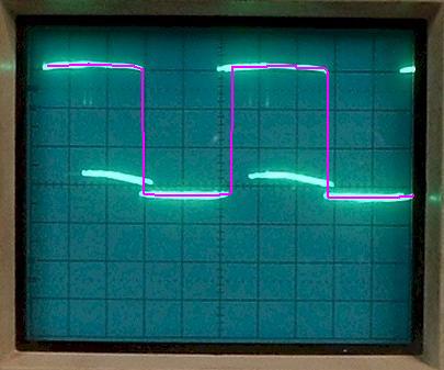
Here there is little to no shunting on any phases, so this one phase has two zero-crossings per cycle as would be expected.
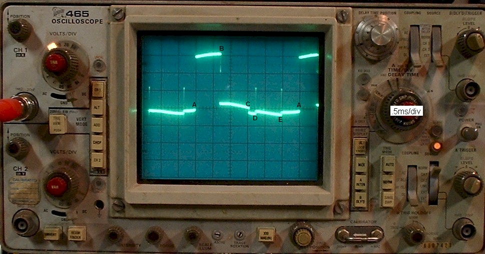
Here there is much more shunting. Notice there are spikes on this phase when another phases gets shunted. these spikes cross zero, albeit very briefly. So then you would be back to making essentially another noise filter.
Then of course there is still the conversion from 12 pulses per revolution to 4 or whatever the tachometer requires. It just seems easier to use the ignition for off-the-shelf automotive tachometers. I certainly don't mean to say it can't be done, I just don't think it would be easier than the currently available options.
Here there is little to no shunting on any phases, so this one phase has two zero-crossings per cycle as would be expected.
Here there is much more shunting. Notice there are spikes on this phase when another phases gets shunted. these spikes cross zero, albeit very briefly. So then you would be back to making essentially another noise filter.
Then of course there is still the conversion from 12 pulses per revolution to 4 or whatever the tachometer requires. It just seems easier to use the ignition for off-the-shelf automotive tachometers. I certainly don't mean to say it can't be done, I just don't think it would be easier than the currently available options.
1981 KZ550 D1 gpz.
Kz550 valve train warning.
Other links.
Kz550 valve train warning.
Other links.
Please Log in or Create an account to join the conversation.
- loudhvx
-
- Offline
- KZr Legend
-
Registered
- Posts: 10863
- Thanks: 1622
Re: De-twitching an electronic tachometer
15 Mar 2018 08:31
I don't seem to be able replicate the low signal output I thought I had earlier. But I don't really know which chip I was using. It may also have been due to the 22.k / 220k confusion producing what looked like a low signal or it may have been the signal shown below that is nearly straight-line, but closer to the supply voltage.
However, with a Dyna S type signal I also don't get the same results as yours unless I tweak the input signal to a very idealized one, one that would not really exist on the bike. The problem in this case, still, is with using the reset function for input. The circuit is dependent on the internal construction of the of the chip, which may not be the same for all chips.
The Dyna S signal, like most/all igniter driver signals, does not go to zero volts. It gets down to the typical 1 volt or so and is current-dependent. This leads to some erratic results when driving the reset with the input signal, as seen below.
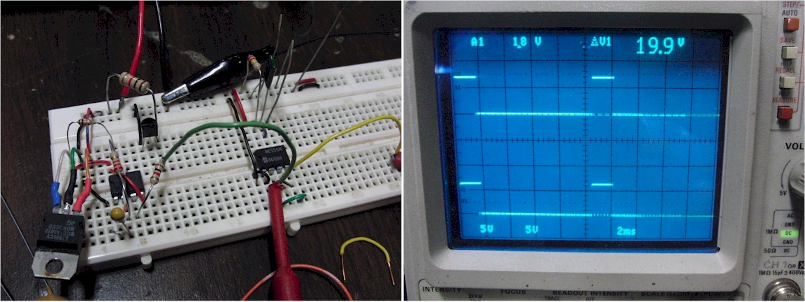
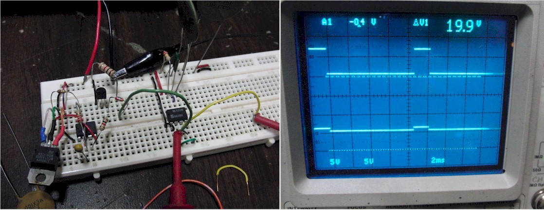
Here is the replication of your results using what I consider to be an overly-idealized input signal.
Input trace is on top. Output trace is on bottom. Both are on 5v scale. The voltage reference lines are there to show 0v reference for each signal.
Here is the output with a slower RPM.
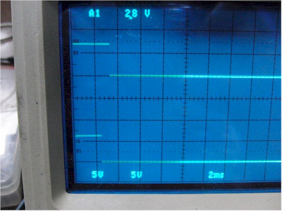
Here I've added one diode to model the Dyna S signal a little more realistically.
Note the input signal never goes to zero, but is just slightly above zero volts. Note the output of the chip is very different than in the previous trial.
Here I've added one more diode to go slightly beyond the what the model for a Dyna S may look like, but could still exist depending on connections etc.
Note the output is now completely inverted into the textbook version of a debounce circuit.
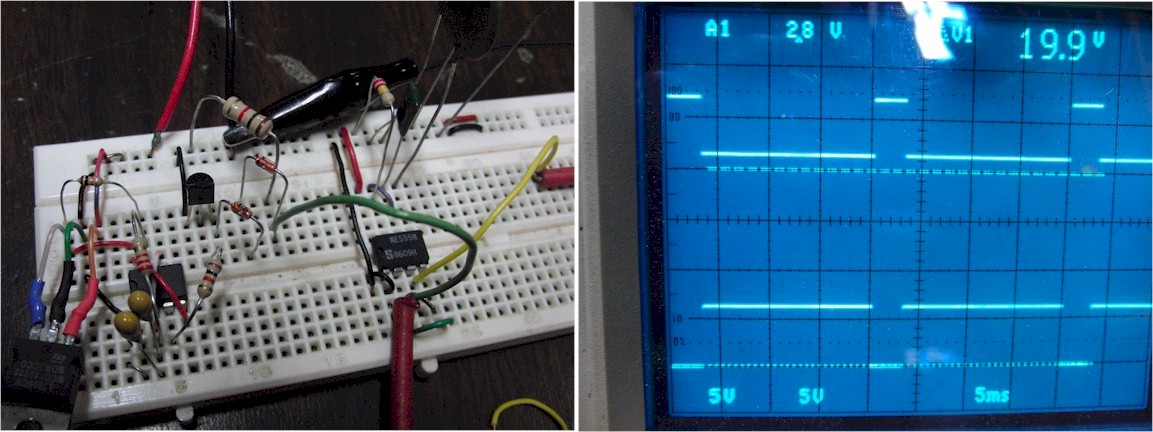
So with just slight alterations to the input, the output goes through radical changes. This means the circuit could conceivably change modes during operation. These problems can likely be overcome, but again, at the cost of more parts etc.
And the other issue of pulse-width changes is still present. In either of the methods (positive or inverted), the Dyna S signal alters the pulse width at higher RPMs or all RPMs, respectively. This is evident in your video as well. I think you noted it. So in any case, there needs to be more parts to get the circuit to be an edge detector, and be immune to varying pulse widths at higher RPMs.
This also doesn't address the high-voltage issue which will require a few additional components as well.
However, with a Dyna S type signal I also don't get the same results as yours unless I tweak the input signal to a very idealized one, one that would not really exist on the bike. The problem in this case, still, is with using the reset function for input. The circuit is dependent on the internal construction of the of the chip, which may not be the same for all chips.
The Dyna S signal, like most/all igniter driver signals, does not go to zero volts. It gets down to the typical 1 volt or so and is current-dependent. This leads to some erratic results when driving the reset with the input signal, as seen below.
Here is the replication of your results using what I consider to be an overly-idealized input signal.
Input trace is on top. Output trace is on bottom. Both are on 5v scale. The voltage reference lines are there to show 0v reference for each signal.
Here is the output with a slower RPM.
Here I've added one diode to model the Dyna S signal a little more realistically.
Note the input signal never goes to zero, but is just slightly above zero volts. Note the output of the chip is very different than in the previous trial.
Here I've added one more diode to go slightly beyond the what the model for a Dyna S may look like, but could still exist depending on connections etc.
Note the output is now completely inverted into the textbook version of a debounce circuit.
So with just slight alterations to the input, the output goes through radical changes. This means the circuit could conceivably change modes during operation. These problems can likely be overcome, but again, at the cost of more parts etc.
And the other issue of pulse-width changes is still present. In either of the methods (positive or inverted), the Dyna S signal alters the pulse width at higher RPMs or all RPMs, respectively. This is evident in your video as well. I think you noted it. So in any case, there needs to be more parts to get the circuit to be an edge detector, and be immune to varying pulse widths at higher RPMs.
This also doesn't address the high-voltage issue which will require a few additional components as well.
1981 KZ550 D1 gpz.
Kz550 valve train warning.
Other links.
Kz550 valve train warning.
Other links.
Please Log in or Create an account to join the conversation.
- weeZee
-
Topic Author
- Offline
- User
-
Registered
- Posts: 81
- Thanks: 22
Re: De-twitching an electronic tachometer
16 Mar 2018 14:06
Quick response, looks like you're using a NE555N as well. This behaviour works with the rather underdocumented difference between reset and trigger voltage input levels, manufacturers may well decide these are not worthwhile parameters to maintain between batches.
Most of my testing was done with an idealised 555 test signal, I can well believe that a noisier signal (e.g. Dyna with ringing at the switching point) might lead to less predictable output. I'm using a clean 12v tach signal from a prototype igniter.
Most of my testing was done with an idealised 555 test signal, I can well believe that a noisier signal (e.g. Dyna with ringing at the switching point) might lead to less predictable output. I'm using a clean 12v tach signal from a prototype igniter.
Please Log in or Create an account to join the conversation.
- weeZee
-
Topic Author
- Offline
- User
-
Registered
- Posts: 81
- Thanks: 22
Re: De-twitching an electronic tachometer
16 Mar 2018 15:19
I see what you mean with multiple voltage signals at shunting crossover, I guess you'd need some hysteresis at the threshold.
I'm not so convinced by the spikes on the last signal image, is this possibly an impedance matching issue with the scope probes?
Like I say, the stator signal seems to be a cleaner signal with less ringing at the switchover than does an IGBT-connected inductive coil voltage signal.
I had entirely forgotten about the number of poles on the stator, so the extra overhead of a frequency divider is a negative.
The following user(s) said Thank You: Scirocco
Please Log in or Create an account to join the conversation.
- loudhvx
-
- Offline
- KZr Legend
-
Registered
- Posts: 10863
- Thanks: 1622
Re: De-twitching an electronic tachometer
20 Mar 2018 19:09
The one in the photo is a Ne555, but that is not necessarily what I used earlier. I've had that board cleared a few times with different projects in the interim. I have some old stock 555's rolling around in the parts box. The earlier steady-low could also have been a misinterpretation of the 22k/220k confusion.
I've had other issues with using the reset pin as a signal input in the past. I generally avoid it.
As far as the stator goes, I would assume the signal was slow enough that impedance mismatch wouldn't really cause the spikes, but I can't say for sure. It would be interesting to expand one of those spikes to see if it's a series of spikes or a single isolated spike.
1981 KZ550 D1 gpz.
Kz550 valve train warning.
Other links.
Kz550 valve train warning.
Other links.
Please Log in or Create an account to join the conversation.
- Scirocco
-
- Offline
- Premium Member
-

Registered
- Never change a running system
- Posts: 4397
- Thanks: 2262
Re: De-twitching an electronic tachometer
08 Jun 2018 15:34 - 08 Jun 2018 16:01
Some things need some time and hardware to fix the problem.
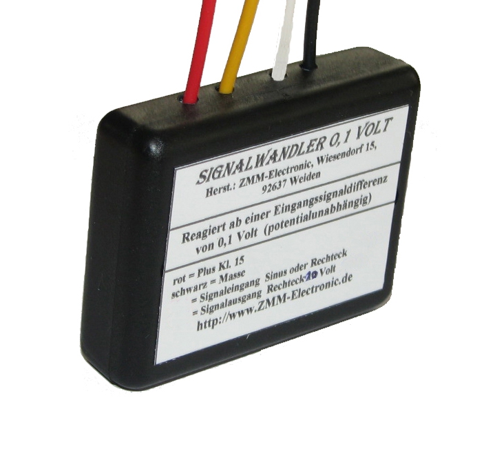
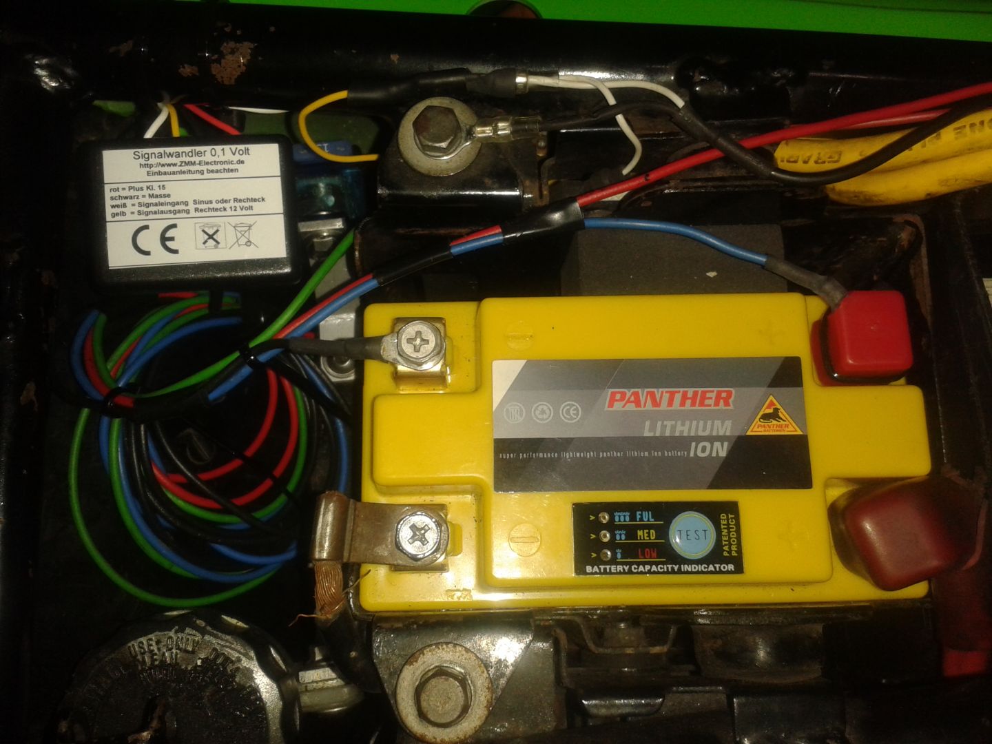
I solve my bouncing rev meter needle/Dyna III problem with a signal converter.
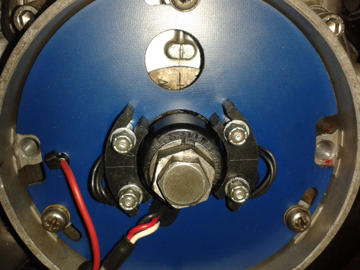
I soldered a wire to one of the Dyna pick-ups on the backside.
Output is 0,50 - 0,80 Volts square wave with an oscilloscope detected.
The converter, (min. 0,10 Volt input square/sinus/triangular signal = ABS sensor), transforms the signal to a 12 Volt square signal,perfect for my KOSO RX2N+
What should i say it works like a puring cat!!!
Thank you a lot weeZee and loudhvx for the technical support and explanations.
Your both are great electronic master brains!!!
Michael
I solve my bouncing rev meter needle/Dyna III problem with a signal converter.
I soldered a wire to one of the Dyna pick-ups on the backside.
Output is 0,50 - 0,80 Volts square wave with an oscilloscope detected.
The converter, (min. 0,10 Volt input square/sinus/triangular signal = ABS sensor), transforms the signal to a 12 Volt square signal,perfect for my KOSO RX2N+
What should i say it works like a puring cat!!!
Thank you a lot weeZee and loudhvx for the technical support and explanations.
Your both are great electronic master brains!!!
Michael
My 1975 Z 1 B 900 Project
www.kzrider.com/forum/11-projects/605133...ears-deep-sleep-mode
www.kzrider.com/forum/11-projects/605133...ears-deep-sleep-mode
Last edit: 08 Jun 2018 16:01 by Scirocco.
Please Log in or Create an account to join the conversation.
- loudhvx
-
- Offline
- KZr Legend
-
Registered
- Posts: 10863
- Thanks: 1622
Re: De-twitching an electronic tachometer
09 Jun 2018 17:20
Glad it's working!
BTW, the rotor on your Dyna looks a little "fuzzy". Are those metal filing?
A good way to remove metal filings from a magnet is masking tape. I learned that trick on speaker magnets.
BTW, the rotor on your Dyna looks a little "fuzzy". Are those metal filing?
A good way to remove metal filings from a magnet is masking tape. I learned that trick on speaker magnets.
1981 KZ550 D1 gpz.
Kz550 valve train warning.
Other links.
Kz550 valve train warning.
Other links.
Please Log in or Create an account to join the conversation.
- Scirocco
-
- Offline
- Premium Member
-
Registered
- Never change a running system
- Posts: 4397
- Thanks: 2262
Re: De-twitching an electronic tachometer
09 Jun 2018 17:31 - 09 Jun 2018 17:34
Thanks loudhvx
Your so called metal filing on the rotor are harmless grease marks, (i put some grease on the advancer).
A German proverb says grease good = drive good without problems.
Your so called metal filing on the rotor are harmless grease marks, (i put some grease on the advancer).
A German proverb says grease good = drive good without problems.
My 1975 Z 1 B 900 Project
www.kzrider.com/forum/11-projects/605133...ears-deep-sleep-mode
www.kzrider.com/forum/11-projects/605133...ears-deep-sleep-mode
Last edit: 09 Jun 2018 17:34 by Scirocco.
The following user(s) said Thank You: loudhvx
Please Log in or Create an account to join the conversation.
- loudhvx
-
- Offline
- KZr Legend
-
Registered
- Posts: 10863
- Thanks: 1622
Re: De-twitching an electronic tachometer
09 Jun 2018 17:35
Ahh
1981 KZ550 D1 gpz.
Kz550 valve train warning.
Other links.
Kz550 valve train warning.
Other links.
The following user(s) said Thank You: Scirocco
Please Log in or Create an account to join the conversation.
- Scirocco
-
- Offline
- Premium Member
-
Registered
- Never change a running system
- Posts: 4397
- Thanks: 2262
Re: De-twitching an electronic tachometer
09 Jun 2018 17:40
I have to replicate to you and weeZee, thank you for the technical support.
A very thankful Michael
A very thankful Michael
My 1975 Z 1 B 900 Project
www.kzrider.com/forum/11-projects/605133...ears-deep-sleep-mode
www.kzrider.com/forum/11-projects/605133...ears-deep-sleep-mode
The following user(s) said Thank You: loudhvx
Please Log in or Create an account to join the conversation.
Moderators: Street Fighter LTD