
ZX550A1 Igniter Pinout
- loudhvx
-

- Offline
- KZr Legend
-

Registered
- Posts: 10864
- Thanks: 1619
Re: IC only works when connected wrong?
07 Oct 2013 13:12Paroxyst wrote:Motor Head wrote: ....
"Compression test: 1 120Psi / 2 110Psi / 3 110Psi and 4 105Psi."
Was this done with the throttle held open? Cold or warm? As that would be Low for your engine.
Throttle untouched. Cold engine.
As Motorhead indicated, the throttle should be wide open when doing the compression test.
Warm, the compression should be near 180 psi or so.
1981 KZ550 D1 gpz.
Kz550 valve train warning.
Other links.
Kz550 valve train warning.
Other links.
Please Log in or Create an account to join the conversation.
- loudhvx
-
- Offline
- KZr Legend
-
Registered
- Posts: 10864
- Thanks: 1619
Re: IC only works when connected wrong?
07 Oct 2013 13:15 - 07 Oct 2013 13:28Paroxyst wrote: This is what I got with the timing gun/strobo light.(Check picture)

At idle, up to about 1500 rpm (+/- 200) or so, the timing pointer should have been on the "F" line. Your drawing makes it look a little advanced, but maybe your idle is higher than it should be if it's not running correctly.
The advance should increase quickly at first, then slowly all the way to redline.
Attachment AdvanceCurveZX550.JPG not found
1981 KZ550 D1 gpz.
Kz550 valve train warning.
Other links.
Kz550 valve train warning.
Other links.
Attachments:
Last edit: 07 Oct 2013 13:28 by loudhvx.
Please Log in or Create an account to join the conversation.
- Paroxyst
-
 Topic Author
- Offline
- User
-

Registered
- KZ550 -82 B3. KZ550 A1. ZX550A1. CBR600F2
- Posts: 64
- Thanks: 2
Re: IC only works when connected wrong?
07 Oct 2013 13:44loudhvx wrote:Motor Head wrote:loudhvx wrote:Paroxyst wrote: Well that would explain the wrongful connection being mirrorimaged, no? Ill try it tomorrow. Although the two images you uploaded have diff. connection on the numbers 7 and 8.
EDIT NOTE: I have to go verify some of this below, I might have this incorrect since I was constructing a test rig:
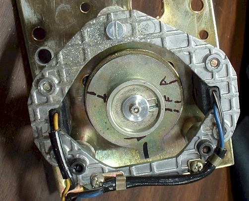
The pickups are removable from the timing plate frame. Make sure the rear (or left as viewed from the right side of the motor) pickup has the blue wire and black/white stripe wires, and the front (or right as viewed from the right side of the motor) pickup has the yellow wire and black wire.
This photo shows the backside of the plate to show the pickup wire colors:
I´ll go and check it out right now, but mind you. The Haynes manual says I should check the yellow and red wire and black and blue wire but it has no red wire from the motor BUT it DOES have the red wire where the plastic contact is on the bike.. bb in 5
Please Log in or Create an account to join the conversation.
- Paroxyst
-
Topic Author
- Offline
- User
-
Registered
- KZ550 -82 B3. KZ550 A1. ZX550A1. CBR600F2
- Posts: 64
- Thanks: 2
Re: IC only works when connected wrong?
07 Oct 2013 13:48 - 07 Oct 2013 13:54
Yes double checked that and it was more on the F-mark when I dropped down the idling a bit. and the advance works fine.
But you do not wonder why the 1-4 igniter coil has + volts on pos AND neg contact while the 2-3 igniter do not?
But you do not wonder why the 1-4 igniter coil has + volts on pos AND neg contact while the 2-3 igniter do not?
Last edit: 07 Oct 2013 13:54 by Paroxyst.
Please Log in or Create an account to join the conversation.
- loudhvx
-
- Offline
- KZr Legend
-
Registered
- Posts: 10864
- Thanks: 1619
Re: IC only works when connected wrong?
07 Oct 2013 13:55
I had to edit this post, unfortunately maybe after you already saw it, so I wanted to make sure you saw the revision, so I'm reposting it.
loudhvx wrote:Motor Head wrote:loudhvx wrote:Paroxyst wrote: Well that would explain the wrongful connection being mirrorimaged, no? Ill try it tomorrow. Although the two images you uploaded have diff. connection on the numbers 7 and 8.
The ZX rotor is one-piece and is keyed to the crank, so it can't be 180 out from the crank unless maybe it was damaged at some point and somebody machined another groove in the rotor, or drilled a new hole in the crank for the roll pin.
Your description of the cams seem to be right, as it would come from the factory.
This is what is also what I said. But the Ignition can still be 180 out by miss timing the cam to crank, using the 2-3 "T" mark for cam timing.
Also as stated he was looking at the #1 cylinder to see the cam lobes pointed away from each other, this is all done from the right/ #4 side. Makes me wonder if the cams are correct.
He has it correct, from his description. When #1 is at TDC, the cam lobes for #1 should be roughly pointing away from each other. This is all on the left cylinder as you sit on the bike.
The thing to look for when looking at the right side of the motor is the notches in the end of the cam shafts. They should be roughly pointing away from each other as well. The cam lobes for #4 will be pointing roughly toward each other.
I have photos in the valve train link in my sig for more clarification.
And with the confirmation that the rotor tooth points toward the rear of the bike when #1 is at TDC, that should mean everything regarding ignition timing is in order, mechanically at least, in the motor.
Since green fires cyl 1 and 4, and black fires 2 and 3, on his bike, which is opposite of what it should be, there must be some electrical issue. I would suspect wiring first, then maybe a bad igniter, then maybe faulty pickups. The igniter uses a combination of moving thresholds and comparators to do timing and dwell, so if something went wrong with that, I imagine it could screw up the timing enough to run way out, but it's still a long stretch.
EDIT NOTE: I have to go verify some of this below. ... ok, it's corrected now.
Ignore the rotor, I had it mounted upside down when I was constructing a test rig (it fit better that way):
The pickups are removable from the timing plate frame. Make sure the rear (or left as viewed from the right side of the motor) pickup has the yellow wire and black wire, and the front (or right as viewed from the right side of the motor) pickup has the blue wire and black/white stripe wires.
1981 KZ550 D1 gpz.
Kz550 valve train warning.
Other links.
Kz550 valve train warning.
Other links.
Please Log in or Create an account to join the conversation.
- loudhvx
-
- Offline
- KZr Legend
-
Registered
- Posts: 10864
- Thanks: 1619
Re: IC only works when connected wrong?
07 Oct 2013 13:57Paroxyst wrote: But you do not wonder why the 1-4 igniter coil has + volts on pos AND neg contact while the 2-3 igniter do not?
Can you specify the exact contacts you are referring to?
1981 KZ550 D1 gpz.
Kz550 valve train warning.
Other links.
Kz550 valve train warning.
Other links.
Please Log in or Create an account to join the conversation.
- Paroxyst
-
Topic Author
- Offline
- User
-
Registered
- KZ550 -82 B3. KZ550 A1. ZX550A1. CBR600F2
- Posts: 64
- Thanks: 2
Re: IC only works when connected wrong?
07 Oct 2013 13:59
EDIT NOTE: I have to go verify some of this below. ... ok, it's corrected now.
Ignore the rotor, I had it mounted upside down when I was constructing a test rig (it fit better that way):
The pickups are removable from the timing plate frame. Make sure the rear (or left as viewed from the right side of the motor) pickup has the yellow wire and black wire, and the front (or right as viewed from the right side of the motor) pickup has the blue wire and black/white stripe wires.
[/quote]
Yes This is what I have aswell. Blue/blackwhite to the front of the bike and yellow/black to the back of the bike. ALTHOUGH when the Yellow and black comes to the firt 4 pole connector the black turnes RED! So either the plate has been changed to a KZ plate or something because that is not Japanmade")
Ignore the rotor, I had it mounted upside down when I was constructing a test rig (it fit better that way):
The pickups are removable from the timing plate frame. Make sure the rear (or left as viewed from the right side of the motor) pickup has the yellow wire and black wire, and the front (or right as viewed from the right side of the motor) pickup has the blue wire and black/white stripe wires.
Yes This is what I have aswell. Blue/blackwhite to the front of the bike and yellow/black to the back of the bike. ALTHOUGH when the Yellow and black comes to the firt 4 pole connector the black turnes RED! So either the plate has been changed to a KZ plate or something because that is not Japanmade
Please Log in or Create an account to join the conversation.
- loudhvx
-
- Offline
- KZr Legend
-
Registered
- Posts: 10864
- Thanks: 1619
Re: IC only works when connected wrong?
07 Oct 2013 14:01 - 22 Jan 2016 07:24
One thing that should be pointed out on my diagram is that the wire colors are very tricky on the ZX550's. Notice that after a connector (marked with a 3 in a little square), the wire colors get swapped. If someone ever tried to fix the harness and noticed the color swaps, and assumed blue goes to blue, etc. in the right combination, the pickups could effectively be swapped.
I think you will have to painstakingly comb through the harness connectors and see what colors connect to what colors.
(Ignore the notation for the ZX400 wiring.)
I think you will have to painstakingly comb through the harness connectors and see what colors connect to what colors.
(Ignore the notation for the ZX400 wiring.)
1981 KZ550 D1 gpz.
Kz550 valve train warning.
Other links.
Kz550 valve train warning.
Other links.
Last edit: 22 Jan 2016 07:24 by Patton. Reason: delete image
The following user(s) said Thank You: Paroxyst
Please Log in or Create an account to join the conversation.
- Paroxyst
-
Topic Author
- Offline
- User
-
Registered
- KZ550 -82 B3. KZ550 A1. ZX550A1. CBR600F2
- Posts: 64
- Thanks: 2
Re: IC only works when connected wrong?
07 Oct 2013 14:04Can you specify the exact contacts you are referring to?
I have the yellow/red cables connected to +/pos on the ignition coils and the green/black connected to -/neg. As one should BUT one of the coils has (tested with a lightbulb) +/pos feed on BOTH positive AND negative connector. The other ignition coil does not.
Please Log in or Create an account to join the conversation.
- Paroxyst
-
Topic Author
- Offline
- User
-
Registered
- KZ550 -82 B3. KZ550 A1. ZX550A1. CBR600F2
- Posts: 64
- Thanks: 2
Re: IC only works when connected wrong?
07 Oct 2013 14:08Ah yes that explains it! Obviously Japanmade after all. Prob. due to prod. costs for using same wiring loom as the KZ´s..maybeOne thing that should be pointed out on my diagram is that the wire colors are very tricky on the ZX550's. Notice that after a connector (marked with a 3 in a little square), the wire colors get swapped.
Please Log in or Create an account to join the conversation.
- loudhvx
-
- Offline
- KZr Legend
-
Registered
- Posts: 10864
- Thanks: 1619
Re: IC only works when connected wrong?
07 Oct 2013 14:11 - 07 Oct 2013 14:14Paroxyst wrote:Can you specify the exact contacts you are referring to?
I have the yellow/red cables connected to +/pos on the ignition coils and the green/black connected to -/neg. As one should BUT one of the coils has (tested with a lightbulb) +/pos feed on BOTH positive AND negative connector. The other ignition coil does not.
That would indicate that one of the ignition drivers (transistor) is shorted out. The yellow/red wire on the coils should be 12v (using battery ground as the reference for the black meter lead). The green wire and black wire should both be at 12v when the crank is not turning, and fluctuate when the crank is turning.
The coil with 12v on only one connector, and 0v on the other, should be getting warm, unless the coil itself is bad. If it's getting warm, that means the igniter transistor is conducting, but it should not be.
Disconnect both wires on the coils and measure the resistance on the + and - terminals of the coils. They should measure about 2.5 to 2.7 ohms. Higher if hotter.
1981 KZ550 D1 gpz.
Kz550 valve train warning.
Other links.
Kz550 valve train warning.
Other links.
Last edit: 07 Oct 2013 14:14 by loudhvx.
Please Log in or Create an account to join the conversation.
- Paroxyst
-
Topic Author
- Offline
- User
-
Registered
- KZ550 -82 B3. KZ550 A1. ZX550A1. CBR600F2
- Posts: 64
- Thanks: 2
Re: IC only works when connected wrong?
07 Oct 2013 14:14 - 07 Oct 2013 14:15Yeah I did that earlier and they both had 2.4+ ohms. Cold!Disconnect both wires on the coils and measure the resistance on the + and - terminals of the coils. They should measure about 2.5 to 2.7 ohms. Higher if hotter.
Last edit: 07 Oct 2013 14:15 by Paroxyst.
Please Log in or Create an account to join the conversation.
Moderators: Street Fighter LTD