
Electrex RO3-02 rotor...opinions please?
- daveo
-
 Topic Author
- Offline
- Premium Member
-

Registered
- Posts: 2950
- Thanks: 761
Electrex RO3-02 rotor...opinions please?
25 Mar 2014 15:39 - 25 Mar 2014 15:40
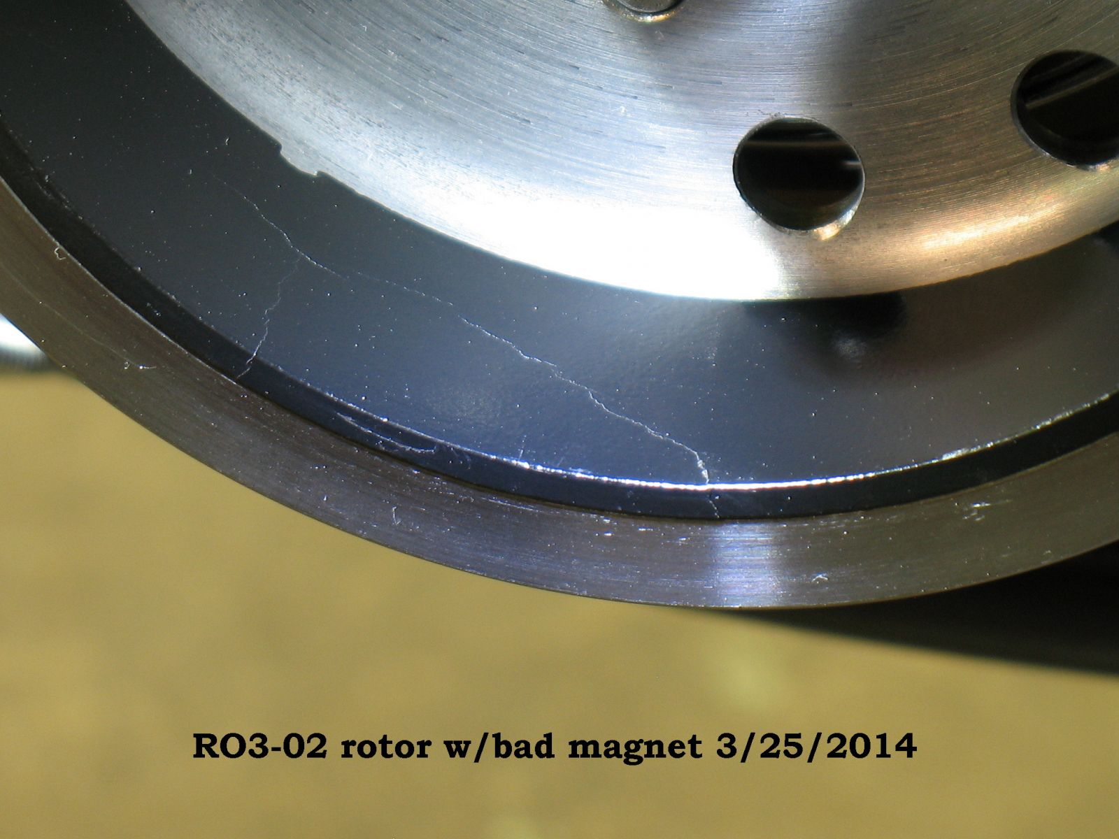
Does anyone think the cracked magnet (see photo) contributes to an ongoing battery charging problem? I have to faithfully recharge the battery after one-two days tops, or it drains while riding. Was going to put a new stator in, and found this...again.
I was under the impression that Electrex World parts are good quality, but this is the second time having magnet issue with the RO3 (RO3-02) rotor, so I'm not so sure.
I was under the impression that Electrex World parts are good quality, but this is the second time having magnet issue with the RO3 (RO3-02) rotor, so I'm not so sure.
1982 KZ1100-A2
Attachments:
Last edit: 25 Mar 2014 15:40 by daveo.
Please Log in or Create an account to join the conversation.
- Patton
-

- Offline
- KZr Legend
-

Registered
- Posts: 18568
- Thanks: 2102
Re: Electrex RO3-02 rotor...opinions please?
25 Mar 2014 17:31
Was the charging system checked by measuring voltage on a fully charged battery (that had recently passed a load test) and found to be 14+ volts at 4000 rpm?
Good Fortune!")
Good Fortune!
1973 Z1
KZ900 LTD
KZ900 LTD
Please Log in or Create an account to join the conversation.
- daveo
-
Topic Author
- Offline
- Premium Member
-
Registered
- Posts: 2950
- Thanks: 761
Re: Electrex RO3-02 rotor...opinions please?
25 Mar 2014 18:43Patton wrote: Was the charging system checked by measuring voltage on a fully charged battery (that had recently passed a load test) and found to be 14+ volts at 4000 rpm?
Good Fortune!
Last summer I checked that with the battery fully charged, and then it showed the voltage increase to 14 volts.
I haven't checked that since, or before pulling the cover, but I really wonder about the effect of having a crack in the magnet, because the bike runs strong until the battery gets drawn down.
1982 KZ1100-A2
Please Log in or Create an account to join the conversation.
- MFolks
-

- Offline
- User
-

Registered
- Posts: 6650
- Thanks: 541
Re: Electrex RO3-02 rotor...opinions please?
25 Mar 2014 20:52
From what I've read about magnets, if they are broken, now you've possibly got polarity in two places, that originally had one.
I'd do this check:
Alternator Testing For the Older 4’s(Z1’s,Kz 900’s, Kz1000’s,Kz1100’s and GPz1100’s).
To check to see if the alternator is working you need to follow these simple steps:
1. Fully charge the battery as this will be the power source during this test.
2. Disconnect the Regulator/Rectifier at the plug that has the six wires in it.
3. Start the engine and let it warm to operating temperature.
4. If you're worried about overheating, position a large fan for cooling the engine.
5. After the engine has reached operating temperature, have a helper assist you, and using a multi-meter, read the output at the three yellow wires (or the alternator output wires)at the disconnected connector.
6. Raise the engine speed to 4000 rpm, and see what the three YELLOW wire combinations(or any alternator output wires) are(1-3, 2-3 & 1-2). The output will be around 50 Volts A.C.(Alternating Current). BE CAREFUL, AS THERE IS A SHOCK HAZARD HERE!!
7. If any of the combinations are low or non-existent, the stator(wire windings) are bad and must be replaced. Some of the older Z1’s and KZ900’s were reported to be phase sensitive, so check the wire colors carefully.
8. Using an OHMETER, Check the three wire combinations again, looking for a reading of 0.36 - 0.54 OHMS. If the readings are above or below, the stator may be bad and need replacement. Also check from any of the three YELLOW wires to ground, this will show if arcing took place. Check only with the engine off !!
9. Before ordering a new stator, check the connections from the stator as there are electrical "Bullet" connectors that may be damaged or dirty. Inspect the wiring for signs of shorting or overheating too. www.z1enterprises.com sells replacement rubber grommets for the alternator output wiring, they get hard and could leak oil after a while.
10. Check the wiring coming out of the grommet as there have been situations where the wires were damaged causing a short(I.E. twisted together with insulation damage).
11. The sprocket cover will have to be removed to access the electrical connectors coming from the alternator, the left foot peg assembly and shifting lever will have to come off also.
Alternator Stator Replacement On the Older 4’s
Source for replacement Stators
A. www.electrosport.com (They have a trouble shooting page)
B. www.customrewind.com
C. www.rmstator.com
D. www.ricksmotorsportselectrics.com
E. www.regulatorrectifier.com
1. If by testing either by checking the output voltage from the stator or by using and ohmmeter for resistance and the stator is determined to be bad, replacing the stator is not a difficult job.
2. The motorcycle owner should have on hand a replacement alternator gasket as it will tear on removal and leak if reused.
3. Put the bike on the center stand if possible and lean it to the right to minimize the oil volume that could come out when the alternator cover is removed.
4. Have selection of Metric wrenches and sockets along with Metric Allen keys to be able to accomplish this repair. ¼" and 3/8" ratchets and extensions may be needed along with Allen bits.
5. Remove the gear shift lever, the sprocket cover and possibly the left foot peg assembly.
6. A catch pan for what little oil will be lost should be positioned under the alternator on the left side. Newspapers will soak up any oil lost or some kitty litter will do as an absorbent.
7. Remove the alternator cover fasteners, some bikes use a socket head cap screw(Allen type) and others use the Phillips head type, the #3 screwdriver bit fits best for those. Use a small dish or can to collect the removed fasteners from the parts to prevent loss/damage.
8. The alternator stator is secured to the inside of the cover usually with three Allen headed bolts, Some bikes may have Torx style fasteners, Remove them and disconnect the three yellow wires that have bullet connectors on them from the bundled wires inside the sprocket cover.
9. If your bike has some color other than yellow for the alternator output wires, make note of what goes where as the older Kawasaki’s were phase sensitive in regard to the regulator/rectifiers.
10. When installing the replacement stator, clock or position the output wires and grommet so they fit into the small port under the alternator cover without being pinched or damaged.
11. Tighten the three Allen or Torx fasteners, securing the replacement stator to the cover. I like using the BLUE Loctite # 242 for hardware that can be removed with hand tools.
12. Remove the old gasket from the mating surfaces of the alternator cover and engine case by scraping with a piece of sharpened plastic like Lexan or Plexi-glass as these will not gouge the soft Aluminum Cases. Avoid using a metal gasket scraper for this.
13. Position the alternator cover, checking for pinched wiring and install the fasteners with a little silver anti-seize on the threads, tightening to the correct torque.
14. Connect up the output wires to the mating female bullet connectors and while you’re in there, check the routing of the wire bundle that runs through there.
15. Inspect for signs of heat damage to the wire insulation and vibration damage too.
16. The side stand switch, neutral switch, and oil pressure switch wiring are all bundled with the alternator output wiring running above and behind the engine output sprocket. This bundle runs in a channel as it goes up toward the various electrical connections.
17. The regulator/rectifier plug on the 80’s bikes usually has six wires in it:
A. One (1)WHITE with RED stripe, this is the bikes main power wire usually 12 gauge in size.
B. One(1) smaller Brown wire, probably 18 gauge or so, the voltage sense wire for the regulator/rectifier, helps keeping it from overcharging the battery.
C. One(1) BLACK with YELLOW stripe wire, part of the ground circuits, maybe 16 gauge in size.
D. Three(3) YELLOW wires, maybe 14 gauge in size, the alternator output wires going to the regulator/rectifier which converts the Alternating Current(A.C.) to Direct Current(D.C.) using rectification, producing the power to run the motorcycle and charge the battery.
18. Reinstall the sprocket cover, again checking for pinched wires before tightening. Install the shifter on it’s splined shaft checking for proper location, and the left side foot peg assembly.
19. Except for the minor oil spill and reluctant fasteners, it’s not a very difficult job to do.
1982 GPZ1100 B2
General Dynamics/Convair 1983-1993
GLCM BGM-109 Tomahawk, AGM-129A Advanced Cruise Missile (ACM)
General Dynamics/Convair 1983-1993
GLCM BGM-109 Tomahawk, AGM-129A Advanced Cruise Missile (ACM)
The following user(s) said Thank You: daveo
Please Log in or Create an account to join the conversation.
- daveo
-
Topic Author
- Offline
- Premium Member
-
Registered
- Posts: 2950
- Thanks: 761
Re: Electrex RO3-02 rotor...opinions please?
26 Mar 2014 08:44
Response from Electrex:
Hello Dave, this from tehcnical: Cracks in the rotor magnet have no effect on its function.
So, I will proceed with the stator installation with reassured confidence.
Hello Dave, this from tehcnical: Cracks in the rotor magnet have no effect on its function.
So, I will proceed with the stator installation with reassured confidence.
1982 KZ1100-A2
Please Log in or Create an account to join the conversation.
- 650ed
-

- Offline
- User
-
Registered
- Posts: 15339
- Thanks: 2833
Re: Electrex RO3-02 rotor...opinions please?
26 Mar 2014 09:33
I wonder if the cracked pieces will have any effect on the rotor's function if they pop loose and wedge between the rotor and stator? :dry: Ed
1977 KZ650-C1 Original Owner - Stock (with additional invisible FIAMM horn)
Please Log in or Create an account to join the conversation.
- koolaid_kid
-
- Offline
- User
-
Registered
- Posts: 783
- Thanks: 99
Re: Electrex RO3-02 rotor...opinions please?
26 Mar 2014 09:42LOL. Personally, it would not be fitted on any bike I work on/own.650ed wrote: I wonder if the cracked pieces will have any effect on the rotor's function if they pop loose and wedge between the rotor and stator? :dry: Ed
1983 GPz 750
810 Wiseco, Kerker, K&N, DynoJet S3, Accel, Progressive, etc.
810 Wiseco, Kerker, K&N, DynoJet S3, Accel, Progressive, etc.
Please Log in or Create an account to join the conversation.
Moderators: Street Fighter LTD