
KZ 1000 Classic EFI questions...
- Wolfpaak
-
 Topic Author
- Offline
- User
-

Registered
- Posts: 28
- Thanks: 0
KZ 1000 Classic EFI questions...
20 Nov 2013 05:53
I am trying to troubleshoot the EFI system with the Kawasaki troubleshooting manual as a guide. I came to the relay tests and found a typo in it I think. It is an ORIGINAL manual from Kawasaki
In steps 6-7 the relay is connected for the test the same way but the results are contradictory.
Does anyone know how the relay should be connected in step 7 for the results stated for a good relay?
In steps 6-7 the relay is connected for the test the same way but the results are contradictory.
Does anyone know how the relay should be connected in step 7 for the results stated for a good relay?
1980 KZ 1000 Classic EFI
Please Log in or Create an account to join the conversation.
- Wolfpaak
-
Topic Author
- Offline
- User
-
Registered
- Posts: 28
- Thanks: 0
Re: KZ 1000 Classic EFI questions...
20 Nov 2013 06:01 - 20 Nov 2013 06:06
Here is a scan of the tests and results, I HOPE!
Attachment KZrelaydiagram.jpg not found
1980 KZ 1000 Classic EFI
Attachments:
Last edit: 20 Nov 2013 06:06 by Wolfpaak.
Please Log in or Create an account to join the conversation.
- MFolks
-

- Offline
- User
-
Registered
- Posts: 6650
- Thanks: 541
Re: KZ 1000 Classic EFI questions...
20 Nov 2013 11:05
I believe I've found a replacement relay, if your's has gone bad:
Fuel Injection Combination Relay
Bosch Fuel Injection Combination Relay W0133-1615089
I'd imagine any place that sells Bosch FI parts can get this relay for you.
Fuel Injection Combination Relay
Bosch Fuel Injection Combination Relay W0133-1615089
I'd imagine any place that sells Bosch FI parts can get this relay for you.
1982 GPZ1100 B2
General Dynamics/Convair 1983-1993
GLCM BGM-109 Tomahawk, AGM-129A Advanced Cruise Missile (ACM)
General Dynamics/Convair 1983-1993
GLCM BGM-109 Tomahawk, AGM-129A Advanced Cruise Missile (ACM)
Please Log in or Create an account to join the conversation.
- Wolfpaak
-
Topic Author
- Offline
- User
-
Registered
- Posts: 28
- Thanks: 0
Re: KZ 1000 Classic EFI questions...
20 Nov 2013 13:37
Thanks for that info! The relay I have tests out ok through step 6 and 8 but would like to know if it's ok on step 7.
1980 KZ 1000 Classic EFI
Please Log in or Create an account to join the conversation.
- DOHC
-

- Offline
- Sustaining Member
-

Registered
- Those Doe-Hawks really go!
- Posts: 1255
- Thanks: 593
Re: KZ 1000 Classic EFI questions...
20 Nov 2013 13:47 - 20 Nov 2013 13:48
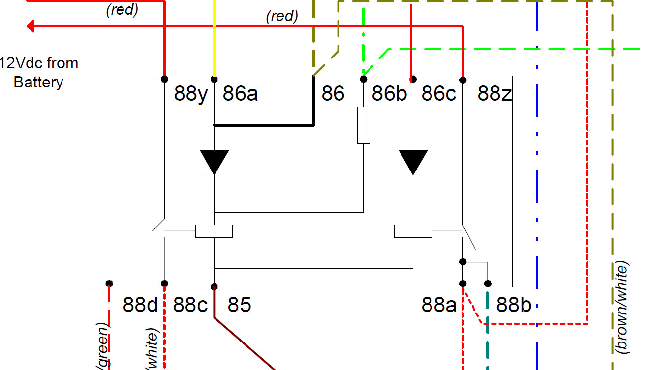
Here is a picture of what might be the internal structure of the relay:
I took that image from this document:
bowlsby.net/914/Classic/zTN_Man08.pdf
It looks like terminals 86a & 85 are the coil for one of the relays. But there is a diode in series with this connection. I suspect that steps #6 and #7 are attempting to test that this diode is working.
I think the error in the manual is in step #7. I think the positive and negative terminals are supposed to be reversed (negative to 85, positive to 86a).
That is:
Step 6. With 12V positive terminal connected to 85, neg to 86a, the relay contact should be open (88y to 88d open circuit).
Step 7: With 12V positive terminal connected to 86a, neg to 85, the relay contact should be closed (88y to 88d short circuit).
Can you post the rest of the steps for testing the relay? I'm not sure what step 8 is getting at. It looks like terminal 86b bypasses the diode, but I can't tell if it has an internal resistor or another coil...
'78 Z1-R in blue
, '78 Z1-R in black,
'78 Z1-R in pieces
My dad's '74 Z1
'00 ZRX1100
My dad's '74 Z1
'00 ZRX1100
Attachments:
Last edit: 20 Nov 2013 13:48 by DOHC. Reason: formatting
The following user(s) said Thank You: Wolfpaak
Please Log in or Create an account to join the conversation.
- Wolfpaak
-
Topic Author
- Offline
- User
-
Registered
- Posts: 28
- Thanks: 0
Re: KZ 1000 Classic EFI questions...
21 Nov 2013 07:02
DOHC here are the scans of the first tests and a new #7 test that my brother figured out from the schematic you supplied.
Attachment scan0001.jpg not found
Attachment scan0002.jpg not found
Attachment scan0003.jpg not found
1980 KZ 1000 Classic EFI
Attachments:
Please Log in or Create an account to join the conversation.
- DOHC
-
- Offline
- Sustaining Member
-
Registered
- Those Doe-Hawks really go!
- Posts: 1255
- Thanks: 593
Re: KZ 1000 Classic EFI questions...
21 Nov 2013 09:19 - 21 Nov 2013 09:20
Now that I see all of the tests, I take back my previous suggestion. With the change I previously recommended, steps 5 and 7 would now be redundant.
Here is what it looks like each step is trying to accomplish.
1) Test "main" relay on function (output contacts closed).
2) Test "main" relay off function (output contacts open) Connecting to 88y is odd. Maybe 88y was supposed to be 85 like test #4? Either way the relay should be off.
3) Test "fuel" relay on function (contacts closed).
4) Test "fuel" relay off function (contacts open), and test internal diode.
5) Same as #3, but with alternate relay terminal 86a (86 and 86a internally connected).
6) Same as #4, but with alternate relay terminal 86a.
Since tests #1 through #6 have already tested that both sets of relay contacts open and close, and that both internal diodes are working (especially if test #2 uses terminal 85 instead of 88y), the only thing left to test is the coil connection to terminal 86b. I would expect that tests #7 and #8 were intended to test this terminal, with #7 testing the on state, and #8 testing the coil sensitivity. Adding a bulb in series as shown in #8 would reduce the coil current to a level that apparently is below the threshold for pulling in the contacts and closing the relay (given that the correct result given is open contacts).
So with all of that, my guess is that #7 should actually have the 12V battery connected between terminals 86b and 85? This would match the battery connection in #8, but without the bulb. This would test that the relay closes when the alternate coil input (86b) is used.
'78 Z1-R in blue
, '78 Z1-R in black,
'78 Z1-R in pieces
My dad's '74 Z1
'00 ZRX1100
My dad's '74 Z1
'00 ZRX1100
Last edit: 21 Nov 2013 09:20 by DOHC.
The following user(s) said Thank You: Wolfpaak
Please Log in or Create an account to join the conversation.
- MFolks
-
- Offline
- User
-
Registered
- Posts: 6650
- Thanks: 541
Re: KZ 1000 Classic EFI questions...
21 Nov 2013 09:27
I've read in my 1982 GPz 1100's shop manual, to limit the current, when testing individual injectors. I use a self powered (I believe a 1.5 volt battery powered light), to see if the injector energizing coil works.It should "Click", and you can feel the solenoid move.
1982 GPZ1100 B2
General Dynamics/Convair 1983-1993
GLCM BGM-109 Tomahawk, AGM-129A Advanced Cruise Missile (ACM)
General Dynamics/Convair 1983-1993
GLCM BGM-109 Tomahawk, AGM-129A Advanced Cruise Missile (ACM)
The following user(s) said Thank You: Wolfpaak
Please Log in or Create an account to join the conversation.
- Wolfpaak
-
Topic Author
- Offline
- User
-
Registered
- Posts: 28
- Thanks: 0
Re: KZ 1000 Classic EFI questions...
22 Nov 2013 05:32 - 22 Nov 2013 05:37dohc wrote: Now that I see all of the tests, I take back my previous suggestion. With the change I previously recommended, steps 5 and 7 would now be redundant.
Here is what it looks like each step is trying to accomplish.
1) Test "main" relay on function (output contacts closed).
2) Test "main" relay off function (output contacts open) Connecting to 88y is odd. Maybe 88y was supposed to be 85 like test #4? Either way the relay should be off.
3) Test "fuel" relay on function (contacts closed).
4) Test "fuel" relay off function (contacts open), and test internal diode.
5) Same as #3, but with alternate relay terminal 86a (86 and 86a internally connected).
6) Same as #4, but with alternate relay terminal 86a.
Since tests #1 through #6 have already tested that both sets of relay contacts open and close, and that both internal diodes are working (especially if test #2 uses terminal 85 instead of 88y), the only thing left to test is the coil connection to terminal 86b. I would expect that tests #7 and #8 were intended to test this terminal, with #7 testing the on state, and #8 testing the coil sensitivity. Adding a bulb in series as shown in #8 would reduce the coil current to a level that apparently is below the threshold for pulling in the contacts and closing the relay (given that the correct result given is open contacts).
So with all of that, my guess is that #7 should actually have the 12V battery connected between terminals 86b and 85? This would match the battery connection in #8, but without the bulb. This would test that the relay closes when the alternate coil input (86b) is used.
Thanks for doing all that research for me!!! Electrical is NOT my strong suit! I believe its magic!!!
Then do I hook up the meter the same way as in 8 also?
I will print your test and put it into my TS manual for future reference!
Later,
Kenny
1980 KZ 1000 Classic EFI
Last edit: 22 Nov 2013 05:37 by Wolfpaak. Reason: Added question
Please Log in or Create an account to join the conversation.
- DOHC
-
- Offline
- Sustaining Member
-
Registered
- Those Doe-Hawks really go!
- Posts: 1255
- Thanks: 593
Re: KZ 1000 Classic EFI questions...
22 Nov 2013 21:30Wolfpaak wrote: Thanks for doing all that research for me!!! Electrical is NOT my strong suit! I believe its magic!!!
Yeah, I think it's largely magic as well... but it's what I do for a living.
")
Wolfpaak wrote: Then do I hook up the meter the same way as in 8 also?
Yes (if my guess is correct) in step #7 the meter would be connected in the same was as step #8.
'78 Z1-R in blue
, '78 Z1-R in black,
'78 Z1-R in pieces
My dad's '74 Z1
'00 ZRX1100
My dad's '74 Z1
'00 ZRX1100
Please Log in or Create an account to join the conversation.
- Wolfpaak
-
Topic Author
- Offline
- User
-
Registered
- Posts: 28
- Thanks: 0
Re: KZ 1000 Classic EFI questions...
24 Nov 2013 07:50dohc wrote:Wolfpaak wrote: Thanks for doing all that research for me!!! Electrical is NOT my strong suit! I believe its magic!!!
Yeah, I think it's largely magic as well... but it's what I do for a living.
Wolfpaak wrote: Then do I hook up the meter the same way as in 8 also?
Yes (if my guess is correct) in step #7 the meter would be connected in the same was as step #8.
Well, Magic smoke came out of the relay when I hooked up the battery as in 8 without the light...Good thing I tried on a spare I had. DOHC not blaming you for anything I am truly grateful for all of your help!!! I do have another relay that has tested good thru all the other tests so will put it in and go from there.
Kenny
1980 KZ 1000 Classic EFI
Please Log in or Create an account to join the conversation.
- DOHC
-
- Offline
- Sustaining Member
-
Registered
- Those Doe-Hawks really go!
- Posts: 1255
- Thanks: 593
Re: KZ 1000 Classic EFI questions...
27 Nov 2013 14:17Wolfpaak wrote: Well, Magic smoke came out of the relay when I hooked up the battery as in 8 without the light...
Aaarg! No way! I'm sorry about that. I considered that possibility and convinced myself that it should be safe to directly connect 12V. That L-JETRONIC wiring diagram which shows the relay internals also shows that terminal 86b is directly connected to 12V when the engine is running. It may be that the relay diagram shown is similar but not identical to the relay used in your Kz, or maybe there i s a current limiting components in that system that is not shown in the diagram. Anyway, I'm sorry you smoked your relay. :S
'78 Z1-R in blue
, '78 Z1-R in black,
'78 Z1-R in pieces
My dad's '74 Z1
'00 ZRX1100
My dad's '74 Z1
'00 ZRX1100
Please Log in or Create an account to join the conversation.
Moderators: Street Fighter LTD