
Project Bike - Starter Wiring Question
- dmccray
-
 Topic Author
- Offline
- User
-

Registered
- Posts: 4
- Thanks: 0
Project Bike - Starter Wiring Question
05 Aug 2013 18:05
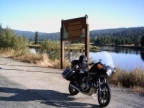
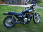
As a little background I bought a 1996 KZ1000P off of craigslist and dove in head first with my first project bike. Figured there was only one way to learn.
The guy that sold me the bike mentioned it only needed a couple of electrical things like a starter solenoid and a few other things. I scoured over some parts diagrams and order parts from Ebay that were missing (i.e right hand controls, IC igniter, starter solenoid, fuse box + fuses and a new battery.) I am at the point that I am trying to at least get engine to crank but am coming up short on the wiring to the starter motor.
I have the solenoid connected to the + battery terminal as well as to the ignition I believe.
In my wiring diagrams it mentions that the solenoid should also connect to the starter motor, however, I do not see any wiring from the starter motor to connect it to. I removed the cover over the starter motor and still no wire. Can someone explain to me what this wire looks like and exactly where on the starter motor it connects to.
I have attached some pictures of the project and the maze of wiring that I am sifting through. I may have bitten off more than I can chew but am determined to take my time and see this project through.
Thank you for your help,
Derrick
Attachment project.JPG not found
The guy that sold me the bike mentioned it only needed a couple of electrical things like a starter solenoid and a few other things. I scoured over some parts diagrams and order parts from Ebay that were missing (i.e right hand controls, IC igniter, starter solenoid, fuse box + fuses and a new battery.) I am at the point that I am trying to at least get engine to crank but am coming up short on the wiring to the starter motor.
I have the solenoid connected to the + battery terminal as well as to the ignition I believe.
Attachment solenoid.jpg not found
In my wiring diagrams it mentions that the solenoid should also connect to the starter motor, however, I do not see any wiring from the starter motor to connect it to. I removed the cover over the starter motor and still no wire. Can someone explain to me what this wire looks like and exactly where on the starter motor it connects to.
Attachment startermotor.jpg not found
I have attached some pictures of the project and the maze of wiring that I am sifting through. I may have bitten off more than I can chew but am determined to take my time and see this project through.
Attachment wiring.JPG not found
Attachment ignitorandcoils.JPG not found
Thank you for your help,
Derrick
Attachments:
Please Log in or Create an account to join the conversation.
- dmccray
-
Topic Author
- Offline
- User
-
Registered
- Posts: 4
- Thanks: 0
Re: Project Bike - Starter Wiring Question
05 Aug 2013 18:13
Oh and as a bit of a follow up what would be the best way to test the individual components in the starting and ignition systems when they are not all hooked up to the wiring harness.
Thanks,
Derrick
Thanks,
Derrick
Please Log in or Create an account to join the conversation.
- MFolks
-

- Offline
- User
-
Registered
- Posts: 6650
- Thanks: 541
Re: Project Bike - Starter Wiring Question
05 Aug 2013 18:13
You're gonna need this webpage for troubleshooting:
www.cyclepsycho.com/kz1000p/kz1000p.html
The starter solenoid will have smaller wires(maybe 16 gauge) for the energizing coil, the large studs/terminals, will need at least 6 AWG(American Wire Gauge) cable. I've found that welding cable is the best to use for this, as it's made up of many fine strands or copper wire, making it very flexible. Most welding supply shops sell it by the foot, and might be able to crimp/swage the correct terminal ends for you, if not, the battery shops should be able to do it for you at a chap price. Just make sure of the cable length, before cutting any.
1982 GPZ1100 B2
General Dynamics/Convair 1983-1993
GLCM BGM-109 Tomahawk, AGM-129A Advanced Cruise Missile (ACM)
General Dynamics/Convair 1983-1993
GLCM BGM-109 Tomahawk, AGM-129A Advanced Cruise Missile (ACM)
The following user(s) said Thank You: dmccray
Please Log in or Create an account to join the conversation.
- MFolks
-
- Offline
- User
-
Registered
- Posts: 6650
- Thanks: 541
Re: Project Bike - Starter Wiring Question
05 Aug 2013 18:16
Ignition Coil Primary And Secondary Wiring
Ignition coils on the 80’s Kz1000,Kz1100’s and Gpz1100’s are wired the same, that is as you sit on the bike, the LEFT ignition coil primary(small wires) are two wires, RED and BLACK. The secondary (or sparkplug wires) go to #1 and #4 sparkplugs(your primary wiring may be different). The 550’s,650’s & 750’s are backwards to what is listed for the bigger 4’s.
The cylinders are numbered left to right as you sit on the seat; #1,#2,#3, and #4.
For the RIGHT ignition coil, the primary wires, again are two wires, RED and GREEN, with the secondary going to #2 and #3.
The RED wire gets it’s voltage from the run/stop switch on the right handlebar switch pod. Your primary wiring may have a different color.
The BLACK and GREEN wires connect to the IC Igniter(if the bike has the Kawasaki supplied electronic ignition) it actually gives the coils their grounds to fire the sparkplugs.
Primary(small wires) side of the coils will read between 1.8 to 3.0 ohms.
Secondary(sparkplug wire ports)side of the coil will read between 10.4K to 15.6K ohms. These ports are wired together, so it makes no difference which is used, as long as the correct coil to sparkplug configuration is followed.
The sparkplug caps should read 5K OHMS(5000), any higher, or a reading of infinity means new caps should be ordered.
To stress the ignition coils, take a hair dryer, heat the coils and see if the ohm readings change from cold to hot . If they do, it’s time to buy new coils.
Keep in mind, the wiring is reversed for the 550’s 650‘s and 750‘s, that is the RIGHT coil primary will be two wires, RED and BLACK with the secondary(sparkplugs) going to #1 and #4.
The LEFT coils primary wiring would be again two wires, RED and GREEN, with the secondary(sparkplugs) going to #2 and #3.
These engines have what is known as a “Wasted Spark” that is, a sparkplug will fire during an exhaust stroke. It does no damage and many other motorcycle engines have this design.
1982 GPZ1100 B2
General Dynamics/Convair 1983-1993
GLCM BGM-109 Tomahawk, AGM-129A Advanced Cruise Missile (ACM)
General Dynamics/Convair 1983-1993
GLCM BGM-109 Tomahawk, AGM-129A Advanced Cruise Missile (ACM)
Please Log in or Create an account to join the conversation.
- MFolks
-
- Offline
- User
-
Registered
- Posts: 6650
- Thanks: 541
Re: Project Bike - Starter Wiring Question
05 Aug 2013 18:19
Alternator Testing For the Older 4’s(Z1’s,Kz 900’s, Kz1000’s,Kz1100’s and GPz1100’s).
To check to see if the alternator is working you need to follow these simple steps:
1. Fully charge the battery as this will be the power source during this test.
2. Disconnect the Regulator/Rectifier at the plug that has the six wires in it.
3. Start the engine and let it warm to operating temperature.
4. If you're worried about overheating, position a large fan for cooling the engine.
5. After the engine has reached operating temperature, have a helper assist you, and using a multi-meter, read the output at the three yellow wires (or the alternator output wires)at the disconnected connector.
6. Raise the engine speed to 4000 rpm, and see what the three YELLOW wire combinations(or any alternator output wires) are(1-3, 2-3 & 1-2). The output will be around 50 Volts A.C.(Alternating Current). BE CAREFUL, AS THERE IS A SHOCK HAZARD HERE!!
7. If any of the combinations are low or non-existent, the stator(wire windings) are bad and must be replaced. Some of the older Z1’s and KZ900’s were reported to be phase sensitive, so check the wire colors carefully.
8. Using an OHMETER, Check the three wire combinations again, looking for a reading of 0.36 - 0.54 OHMS. If the readings are above or below, the stator may be bad and need replacement. Also check from any of the three YELLOW wires to ground, this will show if arcing took place. Check only with the engine off !!
9. Before ordering a new stator, check the connections from the stator as there are electrical "Bullet" connectors that may be damaged or dirty.
Inspect the wiring for signs of shorting or overheating too. www.z1enterprises.com sells replacement rubber grommets for the alternator output wiring, they get hard and could leak oil after a while.
10. Check the wiring coming out of the grommet as there have been situations where the wires were damaged causing a short(I.E. twisted together with insulation damage).
11. The sprocket cover will have to be removed to access the electrical connectors coming from the alternator, the left foot peg assembly and shifting lever will have to come off also.
Alternator Stator Replacement On the Older 4’s
Source for replacement Stators
A. www.electrosport.com (They have a trouble shooting page)
B. www.customrewind.com
C. www.rmstator.com
D. www.ricksmotorsportselectrics.com
E. www.regulatorrectifier.com
1. If by testing either by checking the output voltage from the stator or by using and ohmmeter for resistance and the stator is determined to be bad, replacing the stator is not a difficult job.
2. The motorcycle owner should have on hand a replacement alternator gasket as it will tear on removal and leak if reused.
3. Put the bike on the center stand if possible and lean it to the right to minimize the oil volume that could come out when the alternator cover is removed.
4. Have selection of Metric wrenches and sockets along with Metric Allen keys to be able to accomplish this repair. ¼" and 3/8" ratchets and extensions may be needed along with Allen bits.
5. Remove the gear shift lever, the sprocket cover and possibly the left foot peg assembly.
6. A catch pan for what little oil will be lost should be positioned under the alternator on the left side. Newspapers will soak up any oil lost or some kitty litter will do as an absorbent.
7. Remove the alternator cover fasteners, some bikes use a socket head cap screw(Allen type) and others use the Phillips head type, the #3 screwdriver bit fits best for those. Use a small dish or can to collect the removed fasteners from the parts to prevent loss/damage.
8. The alternator stator is secured to the inside of the cover usually with three Allen headed bolts, Some bikes may have Torx style fasteners, Remove them and disconnect the three yellow wires that have bullet connectors on them from the bundled wires inside the sprocket cover.
9. If your bike has some color other than yellow for the alternator output wires, make note of what goes where as the older Kawasaki’s were phase sensitive in regard to the regulator/rectifiers.
10. When installing the replacement stator, clock or position the output wires and grommet so they fit into the small port under the alternator cover without being pinched or damaged.
11. Tighten the three Allen or Torx fasteners, securing the replacement stator to the cover. I like using the BLUE Loctite # 242 for hardware that can be removed with hand tools.
12. Remove the old gasket from the mating surfaces of the alternator cover and engine case by scraping with a piece of sharpened plastic like Lexan or Plexi-glass as these will not gouge the soft Aluminum Cases. Avoid using a metal gasket scraper for this.
13. Position the alternator cover, checking for pinched wiring and install the fasteners with a little silver anti-seize on the threads, tightening to the correct torque.
14. Connect up the output wires to the mating female bullet connectors and while you’re in there, check the routing of the wire bundle that runs through there.
15. Inspect for signs of heat damage to the wire insulation and vibration damage too.
16. The side stand switch, neutral switch, and oil pressure switch wiring are all bundled with the alternator output wiring running above and behind the engine output sprocket. This bundle runs in a channel as it goes up toward the various electrical connections.
17. The regulator/rectifier plug on the 80’s bikes usually has six wires in it:
A. One (1)WHITE with RED stripe, this is the bikes main power wire usually 12 gauge in size.
B. One(1) smaller Brown wire, probably 18 gauge or so, the voltage sense wire for the regulator/rectifier, helps keeping it from overcharging the battery.
C. One(1) BLACK with YELLOW stripe wire, part of the ground circuits, maybe 16 gauge in size.
D. Three(3) YELLOW wires, maybe 14 gauge in size, the alternator output wires going to the regulator/rectifier which converts the Alternating Current(A.C.) to Direct Current(D.C.) using rectification, producing the power to run the motorcycle and charge the battery.
18. Reinstall the sprocket cover, again checking for pinched wires before tightening. Install the shifter on it’s splined shaft checking for proper location, and the left side foot peg assembly.
19. Except for the minor oil spill and reluctant fasteners, it’s not a very difficult job to do.
1982 GPZ1100 B2
General Dynamics/Convair 1983-1993
GLCM BGM-109 Tomahawk, AGM-129A Advanced Cruise Missile (ACM)
General Dynamics/Convair 1983-1993
GLCM BGM-109 Tomahawk, AGM-129A Advanced Cruise Missile (ACM)
Please Log in or Create an account to join the conversation.
- MFolks
-
- Offline
- User
-
Registered
- Posts: 6650
- Thanks: 541
Re: Project Bike - Starter Wiring Question
05 Aug 2013 18:23
You'll need to do this, probably as you figure out the wiring, as it will make cleaning the connectors much easier:
Cleaning Motorcycle Electrics
Get some of the De-Oxit DN5 electrical contact cleaner and figure on spending a good day going from the front of the bike to the back. It’s a plastic safe cleaner/preservative. www.deoxit.com is their website, and can be purchased at most electronic supply stores.
On the older Kawasaki's, a majority of electrical connectors are inside the headlight housing requiring removal of the headlight, then the fun begins.
Do one set of electrical connectors at a time to avoid mixing up what connects to where. Usually disconnecting, spraying with De-Oxit DN5 and reconnecting is about all you'll need.
However, when encountering the green crud of corrosion, a brass wire brush may be needed on the pins you can reach. Some 400-600 grit wet and dry sandpaper strips rolled into a tube should reach the male and female pins in the more difficult to clean connectors.
Smoker’s pipe cleaners, cotton swabs and wooden toothpicks work as cleaning aids.
Really small electrical connectors may require the use of a welders tip cleaning tool assortment.
Most pins in the connectors are coated with a thin plating of tin, and others may be nothing more than copper or brass.
If moisture is added, the resulting corrosion lowers the voltage/current being carried causing dim lights, slow engine cranking, slow turn signal responce and lower input voltage to the ignition coils resulting in weak spark.
The left and right handlebar switch pods will need attention too as they have circuit functions like turn, horn, run/stop, and start.
Usually a spritz or two with actuation of the switch is about all needed for these switches unless corrosion is detected and then careful disassembly is required.
The ignition switch may or may be not sealed to allow spraying the internal contacts. I urge caution if attempting to open this up as springs, and ball bearings may fly out never to be seen again!
If your bike has the older style glass tubed fuses, I suggest replacing them as vibration can cause internal failure. AGX is the type used, and most auto parts stores can get them for you.
Clean the fuse holder clips, looking for signs of overheating(discolored insulation, signs of melting). I use metal polish on a cotton swab, followed by spraying another clean swab with the De-Oxit DN5 and then rubbing the inside of the fuse clip.
All battery cables must be clean and tight for maximum current transfer. Check the cables going from the Negative(-) battery terminal/post to the engine mounting bolt
Also the one going from the Positive(+) terminal to the starter solenoid and from there to the starter motor.
If any battery cable feels ”Crunchy” when flexed, replace it as possible corrosion is inside the insulation.
Each "Bullet Connector" will have to be sprayed to ensure good connectivity, especially the ones going to the energizing coil of the starter solenoid.
The alternator output “Bullet Connectors” are usually behind the engine sprocket cover and will need inspecting and cleaning too.
The turn signal light sockets will benefit from a spritz from the contact cleaner along with the tail light/brake light socket.
Some brake light switches can be sprayed on the actuating rod, with the spray running down inside to the electrical contacts, others may be sealed requiring replacement if the switch is intermittent in operation.
Some people put the Di-Electric Grease on cleaned terminations/connectors, I don’t, as I’ve read/heard it can cause problems when it gets hot, actually insulating the connections, so the choice is yours to use or not.
I think I've covered about all of the electrical systems on the bike.........
Why WD-40 Should Not Be Used On Motorcycle Electrical Items.
For many years, I was proponent of the use of WD-40 on fuse clips, fuses, switches and connectors. After hearing of other peoples experience with intermittent and sporadic activity, I shrugged it off as maybe they did something wrong in the application of the product.
It wasn’t until the time I rode my 1982 GPz1100 B2 model to downtown San Diego that I encountered the problems others had gone through.
After concluding my business downtown, I walked to where my bike was parked, turned the key to unlock the forks, and prepared to start the engine. The key was in the "On" position, yet I had no lights in the dash panel, the fuel pump was not running(I have FI), and the horn and tail light were not working.
Puzzled as to why nothing electrical was happening, I remember my earlier conversations about how WD-40 will over time become a non-conductor(more like an insulator). I had some pieces of 400 and 600 grit sandpaper in my tool kit and with them was able to scratch away the coating from the WD-40 on the fuses and clips.
After removing the insulating film, the bike started and ran like it should. Since that time, I’ve told people about the problem with WD-40. If you must use a contact cleaner, I recommend getting some "De-oxit" DN5 from Radio Shack Stores or any good electronic supply store.
1982 GPZ1100 B2
General Dynamics/Convair 1983-1993
GLCM BGM-109 Tomahawk, AGM-129A Advanced Cruise Missile (ACM)
General Dynamics/Convair 1983-1993
GLCM BGM-109 Tomahawk, AGM-129A Advanced Cruise Missile (ACM)
Please Log in or Create an account to join the conversation.
- MFolks
-
- Offline
- User
-
Registered
- Posts: 6650
- Thanks: 541
Re: Project Bike - Starter Wiring Question
05 Aug 2013 18:25
Starter Solenoid/Motor Checkout Procedure
Some simple steps to determine what is working and what's not:
1.Fully charge and test the battery(most bike shops can load test the battery, and then use a floating ball hydrometer to check specific gravity in the charged cells).
2.Clean all battery terminals of corrosion.
3.Tighten all starting related connections(Positive RED(+) battery terminal, Negative BLACK(-)terminal) and from the terminal to the engine case. All connections must be clean and tight. If the cables feel “Crunchy” when flexed, they may have corrosion inside the insulation, requiring replacement.
4.Clean the cable from the starter solenoid to the starter motor.
5.Clean and check the "bullet connectors" going to the coil side of the starter solenoid.
6.Try again to start the bike, keep in mind some Kawasaki’s have a clutch interlock to prevent cranking the engine while it’s in gear, so the clutch lever must be squeezed.
7.If no luck, go to step #8
8.Wearing eye protection, bridge with pliers or a screwdriver the two heavy duty(large)terminals on the solenoid. If the bike cranks, your solenoid may be bad.
9. If the starter won’t turn over, one of several things has happened; The starter motor has seized due to brushes binding up, lack of lubrication in the bushings of the motor, the battery is weak , the engine has seized or it could be a combination of any of the above. Some websites for starter motor rebuild kits are:
A. www.mawonline.com/newsite/rick_s_motorsp...-starter_brushes.htm
B. www.psep.biz/store/mitsuba_starter_motors_page_2.htm
10.The dealer may want $$$ for a new solenoid, but take your old one along and visit the nearest riding lawn mower shop. They have solenoids for about $15 that with a little work will fit. Be aware that the new solenoid from the lawn mower shop may require a ground wire for it to work.
11. I’d recommend upgrading from the existing battery cables to at least 6 gauge welding cables.
They are available in two colors(RED and BLACK) have more flexibility due to being constructed with finer conductors, and will fit in tighter areas.
12. The welding cable is sold by the foot, so take careful measurements or bring your old cables along. Most battery shops might be able to supply the cable too, so call to find out. The battery shop should be able to crimp/swage on the end of the welding cable the terminal ends or lugs using either a dedicated crimping machine or a tool that looks like a bolt cutter that has special dies to terminate the cable.
1982 GPZ1100 B2
General Dynamics/Convair 1983-1993
GLCM BGM-109 Tomahawk, AGM-129A Advanced Cruise Missile (ACM)
General Dynamics/Convair 1983-1993
GLCM BGM-109 Tomahawk, AGM-129A Advanced Cruise Missile (ACM)
Please Log in or Create an account to join the conversation.
- MFolks
-
- Offline
- User
-
Registered
- Posts: 6650
- Thanks: 541
Re: Project Bike - Starter Wiring Question
05 Aug 2013 18:30
Color Codes On Most Kawasaki’s (written for 1980’s bikes)
HEADLIGHT
RED with BLACK stripe, High Beam.
RED with YELLOW stripe, Low Beam.
BLACK with YELLOW stripe, the ground circuit.
BRAKE/TAIL LIGHT Can be an # 1157 dual filament bulb
RED, Running or Tail Light.
BLUE,(sometimes with a Red stripe) Brake Light Circuit.
BLACK with YELLOW stripe, the ground circuit.
LEFT FRONT TURN SIGNAL Can be an #1157 dual filament bulb
GREEN, Left front turn signal circuit.
BLUE, Left front running light circuit.
BLACK with YELLOW stripe, the ground circuit.
RIGHT FRONT TURN SIGNAL Can be an # 1157 dual filament bulb
GREY, Right front turn signal circuit.
BLUE, Right front running light circuit.
BLACK with YELLOW stripe, the ground circuit.
LEFT REAR TURN SIGNAL Can be an #1156 single filament bulb
GREEN, Left rear turn signal circuit.
BLACK with YELLOW stripe, the ground circuit.
RIGHT REAR TURN SIGNAL Can be an #1156 single filament bulb
GREY, Right rear turn signal circuit.
BLACK with YELLOW stripe, the ground circuit.
When looking at the picture of the starter motor, I noticed directly above it, that one of the carb holders is cracked, so figure on replacing all 4, as the rest are probably bad too. www.z1enterprises.com is where most of us who own older Kawasaki's get our parts.
1982 GPZ1100 B2
General Dynamics/Convair 1983-1993
GLCM BGM-109 Tomahawk, AGM-129A Advanced Cruise Missile (ACM)
General Dynamics/Convair 1983-1993
GLCM BGM-109 Tomahawk, AGM-129A Advanced Cruise Missile (ACM)
Please Log in or Create an account to join the conversation.
- Motor Head
-
- Offline
- User
-
Registered
- FIX UP YOUR BIKE RIGHT AND CHEAP
- Posts: 5137
- Thanks: 393
Re: Project Bike - Starter Wiring Question
05 Aug 2013 23:56
Do yourself a favor, and buy 4 new intake manifolds. Those in your picture are shot. Probably need to overhaul the carbs, as almost every used bike needs this after sitting.
Starter circuit is like this. Battery positive cable goes to the big post, nut thread, on the solenoid. Then another cable from the d=second big terminal down to the post on the starter. If this connection is made, and the battery is good with the negative cable hooked up to battery and engine block. Then you should be able to jump the two big posts with a solid metal object like a socket extension, and it should spin the motor.
No the two small wires, one goes to ground/ chassis, the other is th power wire from the start button. On your bike it will go through a switch on the clutch lever, so it needs to be pulled in for it to work.
in the one photo your missing the cable on the second Post terminal on the solenoid. There should be a cable coming from the post on the starter to the post on the solenoid.
1982 KZ1000LTD K2 Vance & Hines 4-1 ACCEL COILS Added Vetter fairing & Bags. FOX Racing rear Shocks, Braced Swing-arm, Fork Brace, Progressive Fork Springs RT Gold Emulators, APE Valve Springs, 1166 Big Bore kit, RS34's, GPZ cams.
1980 KZ550LTD C1 Stock SOLD Miss it
1979 MAZDA RX7 in the works, 13B...
1980 KZ550LTD C1 Stock SOLD Miss it
1979 MAZDA RX7 in the works, 13B...
The following user(s) said Thank You: dmccray
Please Log in or Create an account to join the conversation.
- kzz1king
-
- Offline
- User
-
Registered
- Posts: 822
- Thanks: 52
Re: Project Bike - Starter Wiring Question
06 Aug 2013 00:03
MFolks, I noticed this in your post.
"One(1) smaller Brown wire, probably 18 gauge or so, the voltage sense wire for the regulator/rectifier, helps keeping it from overcharging the battery.
I have used reg/rec combos to replace the older Z1/Kz style and have always left the brown wire unhooked. Is there something different I should be doing? Thanks for the informative post,I have saved it.
Wayne
74 Z1 1075, 29 smoothbores, owned and ridden since 1976
Home built KZ1000 turbo setup
www.kzrider.com/forum/11-projects/532476...s-budget-turbo-build
www.kzrider.com/forum/11-projects/532489-74-z-makeover
Home built KZ1000 turbo setup
www.kzrider.com/forum/11-projects/532476...s-budget-turbo-build
www.kzrider.com/forum/11-projects/532489-74-z-makeover
Please Log in or Create an account to join the conversation.
- MFolks
-
- Offline
- User
-
Registered
- Posts: 6650
- Thanks: 541
Re: Project Bike - Starter Wiring Question
06 Aug 2013 00:12
Depending on who made the regulator/rectifier, some have the sense circuit internally, others do not. I'd check with
www.z1enterprises.com
and ask which one do they sell.
1982 GPZ1100 B2
General Dynamics/Convair 1983-1993
GLCM BGM-109 Tomahawk, AGM-129A Advanced Cruise Missile (ACM)
General Dynamics/Convair 1983-1993
GLCM BGM-109 Tomahawk, AGM-129A Advanced Cruise Missile (ACM)
Please Log in or Create an account to join the conversation.
- Motor Head
-
- Offline
- User
-
Registered
- FIX UP YOUR BIKE RIGHT AND CHEAP
- Posts: 5137
- Thanks: 393
Re: Project Bike - Starter Wiring Question
06 Aug 2013 00:26 - 06 Aug 2013 00:26
6 wire R/R with a Brown wire from a Kawasaki, needs the Brown hooked up to a switched battery source. As close to actual battery voltage the better. If you hook it into a circuit with voltage drop, it will see the lower voltage and make up the difference and overcharge the battery.
1982 KZ1000LTD K2 Vance & Hines 4-1 ACCEL COILS Added Vetter fairing & Bags. FOX Racing rear Shocks, Braced Swing-arm, Fork Brace, Progressive Fork Springs RT Gold Emulators, APE Valve Springs, 1166 Big Bore kit, RS34's, GPZ cams.
1980 KZ550LTD C1 Stock SOLD Miss it
1979 MAZDA RX7 in the works, 13B...
1980 KZ550LTD C1 Stock SOLD Miss it
1979 MAZDA RX7 in the works, 13B...
Last edit: 06 Aug 2013 00:26 by Motor Head.
The following user(s) said Thank You: kzz1king
Please Log in or Create an account to join the conversation.
Moderators: Street Fighter LTD