
Charging output low sooty plugs help!
- 1slickKZ1000
-
 Topic Author
- Offline
- User
-

Registered
- Posts: 21
- Thanks: 0
Charging output low sooty plugs help!
03 Dec 2012 01:32
I'm having trouble with my KZ1000-A ('77) missing at high speed (50MPH+) - lower speed rpms seem fine. I've re-powered the coils using wiredgeorge's tech tip, new Accel coils & wires, installed a Dyna S, all with several questions posted other threads but all worked thru with no real problems. After all that, I did not 'fix' the problem... I've found a possible answer, not enough charging voltage at high rpm. It reads between 12.5 vdc to 12.7 vdc no matter the RPM. I started the bike and back probed, with the connector in-place on the blue "Dynamo" stator connector at the 3 braided wires (I think they were once pink, yellow & blue but hard to tell now). I read about 1 ohm resistance between each one.
Then I started the bike and read (again, with the connector still plugged in) about 11 VAC between the same wires (pink to blue, blue to yellow & yellow to pink). Is that the best way to test for A/C volts? If it is, then I'm reading low A/C volts from what I understand. I also ohm checked all 3 to ground and read open on all, so that's good. Anyone have a next step to check or better test than described above?
Then I started the bike and read (again, with the connector still plugged in) about 11 VAC between the same wires (pink to blue, blue to yellow & yellow to pink). Is that the best way to test for A/C volts? If it is, then I'm reading low A/C volts from what I understand. I also ohm checked all 3 to ground and read open on all, so that's good. Anyone have a next step to check or better test than described above?
Please Log in or Create an account to join the conversation.
- 1slickKZ1000
-
Topic Author
- Offline
- User
-
Registered
- Posts: 21
- Thanks: 0
Re: Charging output low sooty plugs help!
03 Dec 2012 01:44
I failed to mention, I got the bike with a replacement rectifier / regulator combo installed (with the stock rectifier removed).
Please Log in or Create an account to join the conversation.
- MFolks
-

- Offline
- User
-
Registered
- Posts: 6650
- Thanks: 541
Re: Charging output low sooty plugs help!
03 Dec 2012 01:55
Alternator Testing For the Older 4’s(Z1’s,Kz 900’s, Kz1000’s,Kz1100’s ,GPz1100’s
And possibly the 750’s).
To check to see if the alternator is working you need to follow these simple steps:
1. Fully charge the battery as this will be the power source during this test.
2. Disconnect the Regulator/Rectifier at the plug that has the six wires in it.
3. Start the engine and let it warm to operating temperature.
4. If you're worried about overheating, position a large fan for cooling the engine.
5. After the engine has reached operating temperature, have a helper assist you, and using a multi-meter, read the output at the three yellow wires (or the alternator output wires)at the disconnected connector.
6. Raise the engine speed to 4000 rpm, and see what the three YELLOW wire combinations(or any alternator output wires) are(1-3, 2-3 & 1-2). The output will be around 50 Volts A.C.(Alternating Current). BE CAREFUL, AS THERE IS A SHOCK HAZARD HERE!! The Alternator produces a three(3) phase A.C. power that is changed to D.C. by the regulator/rectifier, powering the motorcycles electrical system.
7. If any of the combinations are low or non-existent, the stator(wire windings) are bad and must be replaced. Some of the older Z1’s and KZ900’s were reported to be phase sensitive, so check the wire colors carefully.
8. Using an OHMETER, Check the three wire combinations again, looking for a reading of 0.36 - 0.54 OHMS. If the readings are above or below, the stator may be bad and need replacement. Also check from any of the three YELLOW wires to ground, this will show if arcing took place. Check only with the engine off !!
9. Before ordering a new stator, check the connections from the stator as there are electrical "Bullet" connectors that may be damaged or dirty. Inspect the wiring for signs of shorting or overheating too. www.z1enterprises.com sells replacement rubber grommets for the alternator output wiring, they get hard and could leak oil after a while.
10. Check the wiring coming out of the grommet as there have been situations where the wires were damaged causing a short(I.E. twisted together with insulation damage).
11. The sprocket cover will have to be removed to access the electrical connectors coming from the alternator, the left foot peg assembly and shifting lever will have to come off also.
Alternator Stator Replacement On the Older 4’s
Source for replacement Stators
A. www.electrosport.com/technical-resources.../fault-finding-guide
B. www.customrewind.com
C. www.rmstator.com
D. www.regulatorrectifier.com
E. www.oregonmotorcycleparts.com (Rectifier/ Regulators Only)
1. If by testing either by checking the output voltage from the stator or by using and ohmmeter for resistance and the stator is determined to be bad, replacing the stator is not a difficult job.
2. The motorcycle owner should have on hand a replacement alternator gasket as it will tear on removal and leak if reused.
3. Put the bike on the center stand if possible and lean it to the right to minimize the oil volume that could come out when the alternator cover is removed.
4. Have selection of Metric wrenches and sockets along with Metric Allen keys to be able to accomplish this repair. ¼" and 3/8" ratchets and extensions may be needed along with Allen bits.
5. Remove the gear shift lever, the sprocket cover and possibly the left foot peg assembly.
6. A catch pan for what little oil will be lost should be positioned under the alternator on the left side. Newspapers will soak up any oil lost or some kitty litter will do as an absorbent.
7. Remove the alternator cover fasteners, some bikes use a socket head cap screw(Allen type) and others use the Phillips head type, the #3 screwdriver bit fits best for those. Use a small dish or can to collect the removed fasteners from the parts to prevent loss/damage.
8. The alternator stator is secured to the inside of the cover usually with three Allen headed bolts, Some bikes may have Torx style fasteners(looks like a star), Remove them and disconnect the three yellow wires that have bullet connectors on them from the bundled wires inside the sprocket cover.
9. If your bike has some color other than yellow for the alternator output wires, make note of what goes where as the older Kawasaki’s were phase sensitive in regard to the regulator/rectifiers.
10. When installing the replacement stator, clock or position the output wires and grommet so they fit into the small port under the alternator cover without being pinched or damaged.
11. Tighten the three Allen or Torx fasteners, securing the replacement stator to the cover. I like using the BLUE Loctite # 242 for hardware that can be removed with hand tools.
12. Remove the old gasket from the mating surfaces of the alternator cover and engine case by scraping with a piece of sharpened plastic like Lexan or Plexi-glass as these will not gouge the soft Aluminum Cases. Avoid using a metal gasket scraper for this.
13. Position the alternator cover, checking for pinched wiring and install the fasteners with a little silver anti-seize on the threads, tightening to the correct torque.
14. Connect up the output wires to the mating female bullet connectors and while you’re in there, check the routing of the wire bundle that runs through there.
15. Inspect for signs of heat damage to the wire insulation and vibration damage too.
16. The side stand switch, neutral switch, and oil pressure switch wiring are all bundled with the alternator output wiring running above and behind the engine output sprocket. This bundle runs in a channel as it goes up toward the various electrical connections.
17. The regulator/rectifier plug on the 80’s bikes usually has six wires in it:
A. One (1) WHITE with RED stripe, this is the bikes main power wire usually 12 gauge in size.
B. One(1) smaller BROWN wire, probably 18 gauge or so, the voltage sense wire for the regulator/rectifier, helps keeping it from overcharging the battery.
C. One(1) BLACK with YELLOW stripe wire, part of the ground circuits, maybe 16 gauge in size.
D. Three(3) YELLOW wires, maybe 14 gauge in size, the alternator output wires going to the regulator/rectifier which converts the Alternating Current(A.C.) to Direct Current(D.C.) using rectification, producing the power to run the motorcycle and charge the battery.
18. Reinstall the sprocket cover, again checking for pinched wires before tightening. Install the shifter on it’s splined shaft checking for proper location, and the left side foot peg assembly.
19. Except for the minor oil spill and reluctant fasteners, it’s not a very difficult job to do.
A video on testing and troubleshooting a motorcycles charging system:
1982 GPZ1100 B2
General Dynamics/Convair 1983-1993
GLCM BGM-109 Tomahawk, AGM-129A Advanced Cruise Missile (ACM)
General Dynamics/Convair 1983-1993
GLCM BGM-109 Tomahawk, AGM-129A Advanced Cruise Missile (ACM)
The following user(s) said Thank You: BlackZ1R
Please Log in or Create an account to join the conversation.
- MFolks
-
- Offline
- User
-
Registered
- Posts: 6650
- Thanks: 541
Re: Charging output low sooty plugs help!
03 Dec 2012 02:03
These bike's need a fully charged battery to function, if the charging system is weak, you'll get sooty plugs, having you do needless jet and needle clip changing.
If you've never cleaned the electrical connectors and handlebar switches, read this:
Cleaning Motorcycle Electrics
1. Get some of the De-Oxit electrical contact cleaner and figure on spending a good day going from the front of the bike to the back. It’s a plastic safe cleaner/preservative. www.deoxit.com is their website. It can be purchased at most Radio Shack Stores or any electronic supply places. Or use any plastic safe electrical contact cleaner(NOT WD-40 !).
2. On the older Kawasaki's, a majority of electrical connectors are inside the headlight housing requiring removal of the headlight, then the fun begins.
3. Do one set of electrical connectors at a time to avoid mixing up what connects to where. Usually disconnecting, spraying with De-Oxit and reconnecting is about all you'll need.
4. However, when encountering the green crud of corrosion, a brass wire brush may be needed on the pins you can reach. Some 400-600 grit wet and dry sandpaper strips rolled into a tube should reach the male and female pins in the more difficult to clean connectors.
5. Smoker’s pipe cleaners, cotton swabs and wooden toothpicks work as cleaning aids.
6. Really small electrical connectors may require the use of a welders tip cleaning tool assortment.
7. Most pins in the connectors are coated with a thin plating of tin, and others may be nothing more than copper or brass.
8. If moisture is added, the resulting corrosion lowers the voltage/current being carried causing dim lights, slow engine cranking, slow turn signal responce and lower input voltage to the ignition coils resulting in weak spark.
9. The left and right handlebar switch pods will need attention too as they have circuit functions like turn, horn, run/stop, and start. The older Kawasaki’s have reports of the soldered connections crumbling, if your bike has this problem, just ask, as I’ve got a repair procedure for this.
10. Usually a spritz or two with actuation of the switch is about all needed for these switches unless corrosion is detected and then careful disassembly is required.
11. The ignition switch may or may be not sealed to allow spraying the internal contacts. I urge caution if attempting to open this up as springs, and ball bearings may fly out never to be seen again!
12. If your bike has the older style glass tubed fuses, I suggest replacing them as vibration can cause internal failure. AGX is the type used, and most auto parts stores can get them for you, along with boating supply stores.
13. Clean the fuse holder clips, looking for signs of overheating(discolored insulation, signs of melting). I use metal polish on a cotton swab, followed by spraying another clean swab with the De-Oxit and then rubbing the inside of the fuse clip.
14. All battery cables must be clean and tight for maximum current transfer. Check the cables going from the Negative(-) battery terminal/post to the engine mounting bolt
15. Also the one going from the Positive(+) terminal to the starter solenoid and from there to the starter motor.
16. If any battery cable feels ”Crunchy” when flexed, replace it as possible corrosion is inside the insulation. Inspect all heavy duty battery cables and the smaller wire terminations(Bullet Connectors), for failed crimps, and those used in the electrical connectors, as they can fail over time.
17. Each "Bullet Connector" will have to be sprayed to ensure good connectivity, especially the ones going to the energizing coil of the starter solenoid.
18. The alternator output “Bullet Connectors” are usually behind the engine sprocket cover and will need inspecting and cleaning too.
20. The turn signal light sockets will benefit from a spritz from the contact cleaner along with the tail light/brake light socket.
21. Some brake light switches can be sprayed on the actuating rod, with the spray running down inside to the electrical contacts, others may be sealed requiring replacement if the switch is intermittent in operation.
22. Some people put the Di-Electric Grease on cleaned terminations/connectors, I don’t, as I’ve read/heard it can cause problems when it gets hot, actually insulating the connections, so the choice is yours to use or not.
I think I've covered about all of the electrical systems on the bike.........
“I spent a weekend going through every electrical connection and switch on the bike with a little scotchbrite pad and DeOxit - what a difference! Everything was brighter, gauge backlights, indicator lights, turn signals, I was getting a nicer spark, it fired up quicker, etc. Well worth my time. WELL worth it! “
From a forum member at www.kzrider.com
1982 GPZ1100 B2
General Dynamics/Convair 1983-1993
GLCM BGM-109 Tomahawk, AGM-129A Advanced Cruise Missile (ACM)
General Dynamics/Convair 1983-1993
GLCM BGM-109 Tomahawk, AGM-129A Advanced Cruise Missile (ACM)
Please Log in or Create an account to join the conversation.
- 1slickKZ1000
-
Topic Author
- Offline
- User
-
Registered
- Posts: 21
- Thanks: 0
Re: Charging output low sooty plugs help!
03 Dec 2012 02:08
That's good info but I need to figure out how to read the A/C voltage correctly. I don't know if it will run or screw something up (ie rectifier/regulator) when I unplug the blue connector and attempt to start the bike. The blue connector has the 3 stator wires plus two other wires (not clue what they are)....
Please Log in or Create an account to join the conversation.
- MFolks
-
- Offline
- User
-
Registered
- Posts: 6650
- Thanks: 541
Re: Charging output low sooty plugs help!
03 Dec 2012 02:32
Get either a Digital or Analog(the type with the moving needle on the dial) to be able to read the output voltage of the alternator.
Look at this video on how to use a digital multimeter:
The Best Mutimeter Tutorial
(Using a bench top Digital Multimeter)
Look at this video on how to use a digital multimeter:
The Best Mutimeter Tutorial
(Using a bench top Digital Multimeter)
1982 GPZ1100 B2
General Dynamics/Convair 1983-1993
GLCM BGM-109 Tomahawk, AGM-129A Advanced Cruise Missile (ACM)
General Dynamics/Convair 1983-1993
GLCM BGM-109 Tomahawk, AGM-129A Advanced Cruise Missile (ACM)
Please Log in or Create an account to join the conversation.
- Old Man Rock
-
- Offline
- User
-
Registered
- Posts: 6074
- Thanks: 225
Re: Charging output low sooty plugs help!
03 Dec 2012 08:51 - 03 Dec 2012 08:55
Coil Mod huh.... :pinch:
Don't take it personal for I cringe when I hear that was a recommendation... Defeats what you're truly trying to accomplish... Even did a write up on why it's not recommended (File Base)... Ah well back to the subject matter...
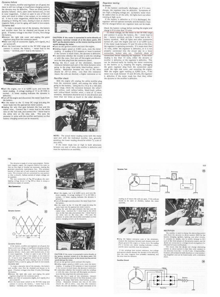
First, download the Z1 service manual, covers Z1, KZ900 and up to 1980 KZ 1000's. Sure there are some minor changes throughout but 98% the same for engine and electrical parts.
Z1, KZ900, KZ1000 OEM Service Manual
Secondly, inusre you have an ideal grounded engine/frame -> regulator connection!
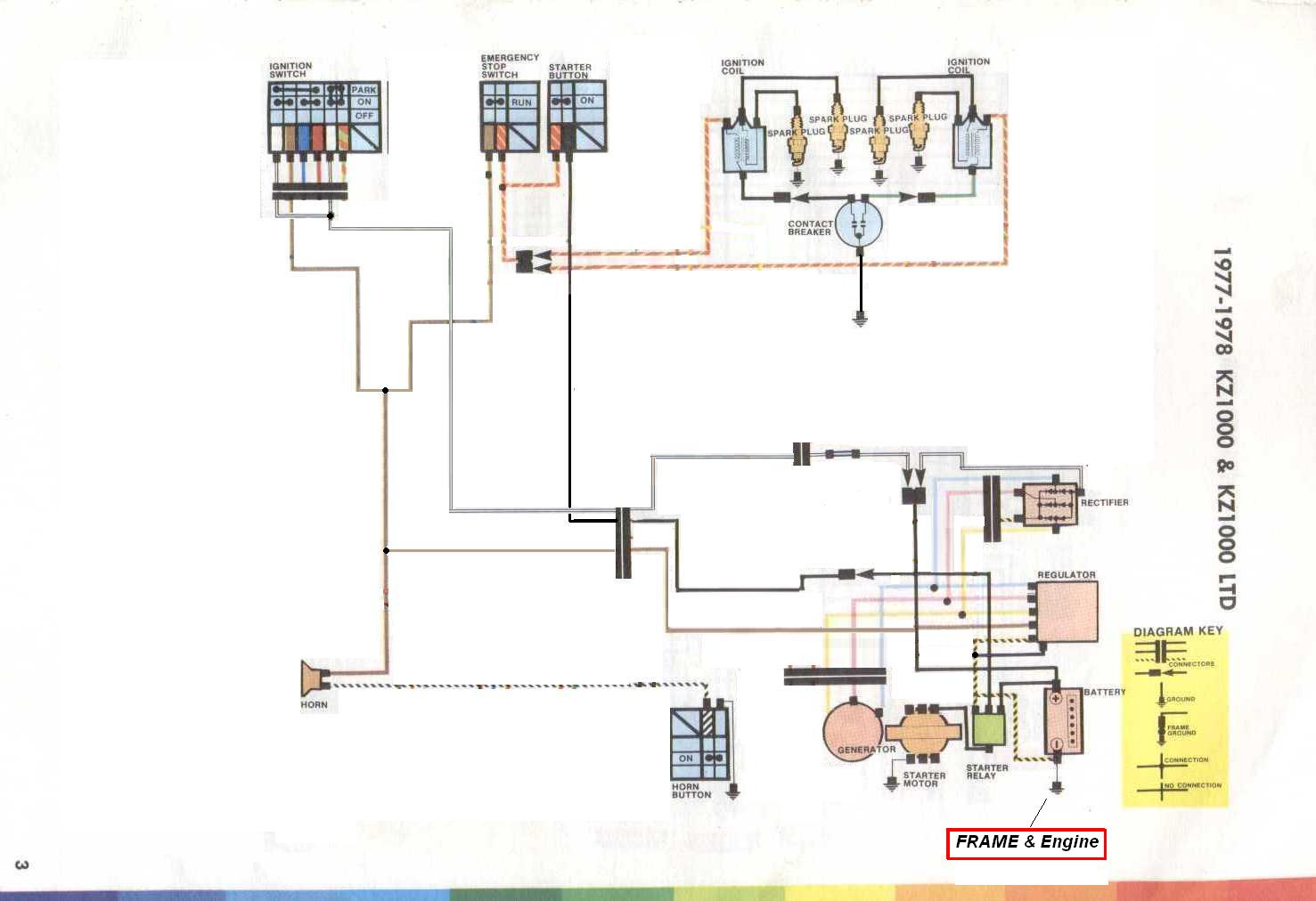
To go along with what Mfolks provided...
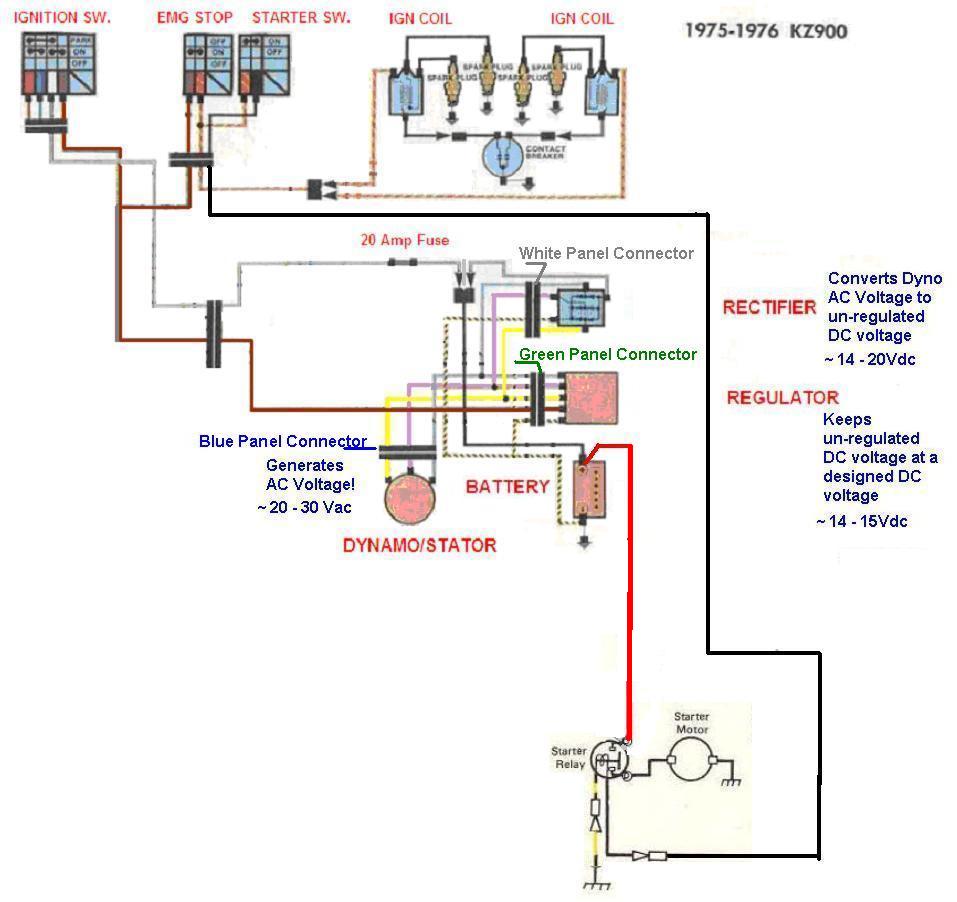
Easier to read wiring diagram with Colored Connector info...
Don't take it personal for I cringe when I hear that was a recommendation... Defeats what you're truly trying to accomplish... Even did a write up on why it's not recommended (File Base)... Ah well back to the subject matter...
First, download the Z1 service manual, covers Z1, KZ900 and up to 1980 KZ 1000's. Sure there are some minor changes throughout but 98% the same for engine and electrical parts.
Z1, KZ900, KZ1000 OEM Service Manual
Secondly, inusre you have an ideal grounded engine/frame -> regulator connection!
To go along with what Mfolks provided...
Easier to read wiring diagram with Colored Connector info...
1976 KZ900-A4
MTC 1075cc.
Camshafts: Kawi GPZ-1100 .375 lift
Head: P&P via Larry Cavanaugh
ZX636 suspension
MIKUNI, RS-34'S...
Kerker 4-1, 1.5" comp baffle.
Dyna-S E.I.
Earls 10 row Oil Cooler
Acewell 2802 Series Speedo/Tach
Innovate LC1 Wideband 02 AFR meter
Phoenix, Az
MTC 1075cc.
Camshafts: Kawi GPZ-1100 .375 lift
Head: P&P via Larry Cavanaugh
ZX636 suspension
MIKUNI, RS-34'S...
Kerker 4-1, 1.5" comp baffle.
Dyna-S E.I.
Earls 10 row Oil Cooler
Acewell 2802 Series Speedo/Tach
Innovate LC1 Wideband 02 AFR meter
Phoenix, Az
Last edit: 03 Dec 2012 08:55 by Old Man Rock.
Please Log in or Create an account to join the conversation.
- 1slickKZ1000
-
Topic Author
- Offline
- User
-
Registered
- Posts: 21
- Thanks: 0
Re: Charging output low sooty plugs help!
03 Dec 2012 15:07
I'm trying to digest all this... What I now think is, if I start the bike and then unplug the blue stator connector, I think the bike will continue to run (with out the lights etc) but then I can measure the A/C voltage between the 3 stator wires. From what I read, I should get about 50 vac. If I do, then I likely have a R/R issue.
Please Log in or Create an account to join the conversation.
- loudhvx
-

- Offline
- KZr Legend
-

Registered
- Posts: 10864
- Thanks: 1619
Re: Charging output low sooty plugs help!
03 Dec 2012 15:17
Correct, the blue connector must be unplugged to do AC voltage testing. With the plug connected, the AC waves turn into square waves. The voltmeter assumes sine waves. The only way to ensure sine waves is to unplug the blue connector. The bike should run like normal with the blue pug unconnected. The lights etc should work like normal. You will, of course, then, only be running on the battery.
Since you can run at low to mid rpms, you should figure out the charging system first, then move on to the RPM problem. They may not be related. If the battery is at 12.7v on the highway, it should be enough voltage to run normal.
Per your PM message, the brown wire is not normally connected directly to the battery. It is a switched 12v source. If the combo reg/rec is a 5 wire (3 ac, bat +, bat -), then ignore the brown wire in the harness side of the reg/rec connector. It should be left open.
1981 KZ550 D1 gpz.
Kz550 valve train warning.
Other links.
Kz550 valve train warning.
Other links.
Please Log in or Create an account to join the conversation.
- 1slickKZ1000
-
Topic Author
- Offline
- User
-
Registered
- Posts: 21
- Thanks: 0
Re: Charging output low sooty plugs help!
03 Dec 2012 15:45
When I un-plugged the blue connector and turned the key on, the warning lights did not come on, so I assume it will run just with no lights... Before I try anything, I'll un-plug the brown wire I now have connected to the battery, and see if any changes. Un-plugging the brown from the green connector came from a thread you helped - it was set up just like mine with the same issues (not turning off with the key). On that thread, the brown was connected to the battery, and it worked (as did mine). Although, I'm having this new issue which may not be related... I'll disconect it and see what happens.
Please Log in or Create an account to join the conversation.
- loudhvx
-
- Offline
- KZr Legend
-
Registered
- Posts: 10864
- Thanks: 1619
Re: Charging output low sooty plugs help!
03 Dec 2012 16:48
The headlight and tail etc should still come on regardless of the blue connector. The only two lights that will likely go out are the oil-pressure light and neutral light. Those two lights use those two other wires you mentioned. All of the other lights should be unaffected.
The issue with the key not turning the bike off, if I recall, were for aftermarket combo reg/recs that had 6 wires (not 5 like yours)... but it's been a while, so my memory could be wrong.
The issue with the key not turning the bike off, if I recall, were for aftermarket combo reg/recs that had 6 wires (not 5 like yours)... but it's been a while, so my memory could be wrong.
1981 KZ550 D1 gpz.
Kz550 valve train warning.
Other links.
Kz550 valve train warning.
Other links.
Please Log in or Create an account to join the conversation.
- 1slickKZ1000
-
Topic Author
- Offline
- User
-
Registered
- Posts: 21
- Thanks: 0
Re: Charging output low sooty plugs help!
03 Dec 2012 18:39loudhvx wrote: The headlight and tail etc should still come on regardless of the blue connector. The only two lights that will likely go out are the oil-pressure light and neutral light. Those two lights use those two other wires you mentioned. All of the other lights should be unaffected.
The issue with the key not turning the bike off, if I recall, were for aftermarket combo reg/recs that had 6 wires (not 5 like yours)... but it's been a while, so my memory could be wrong.
I'm going to attempt to post a link to the thread I was referring to. If for no other reason to explain why & what I did. The meat & potatoes is on the last few posts. I've not learned how to attach a link so we'll see what happens!
kzrider.com/forum/4-electrical/457270-st...0a?limit=20&start=40
Please Log in or Create an account to join the conversation.
Moderators: Street Fighter LTD