
my kz1000 wiring situation
- Ogcoda
-
 Topic Author
- Offline
- User
-

Registered
- Killing Everything
- Posts: 49
- Thanks: 0
my kz1000 wiring situation
14 Nov 2012 03:30
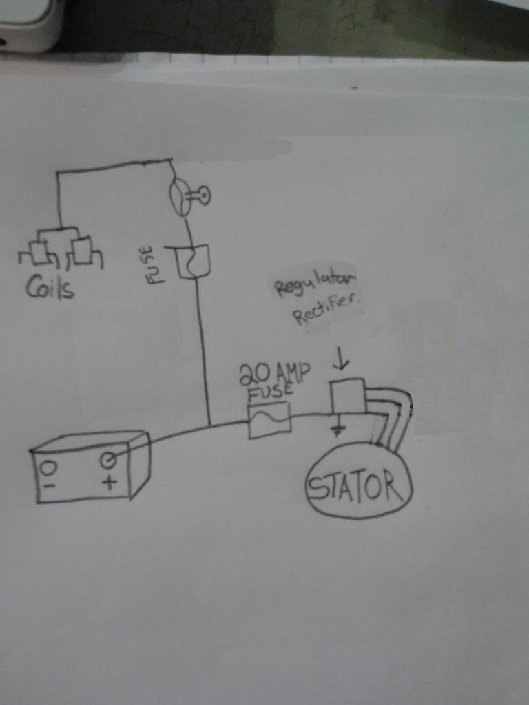
So here is the deal i'm running my wiring like this as of now on my kz.
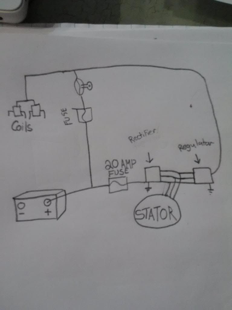
Well the thing is, is that ether the regulator and or rectifier on my bike crapped out on me and i found something that replaces both with one unit buuuuuuuuut
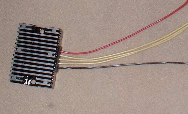
as you can see there is a ground wire, three wires for the stator and a power wire.
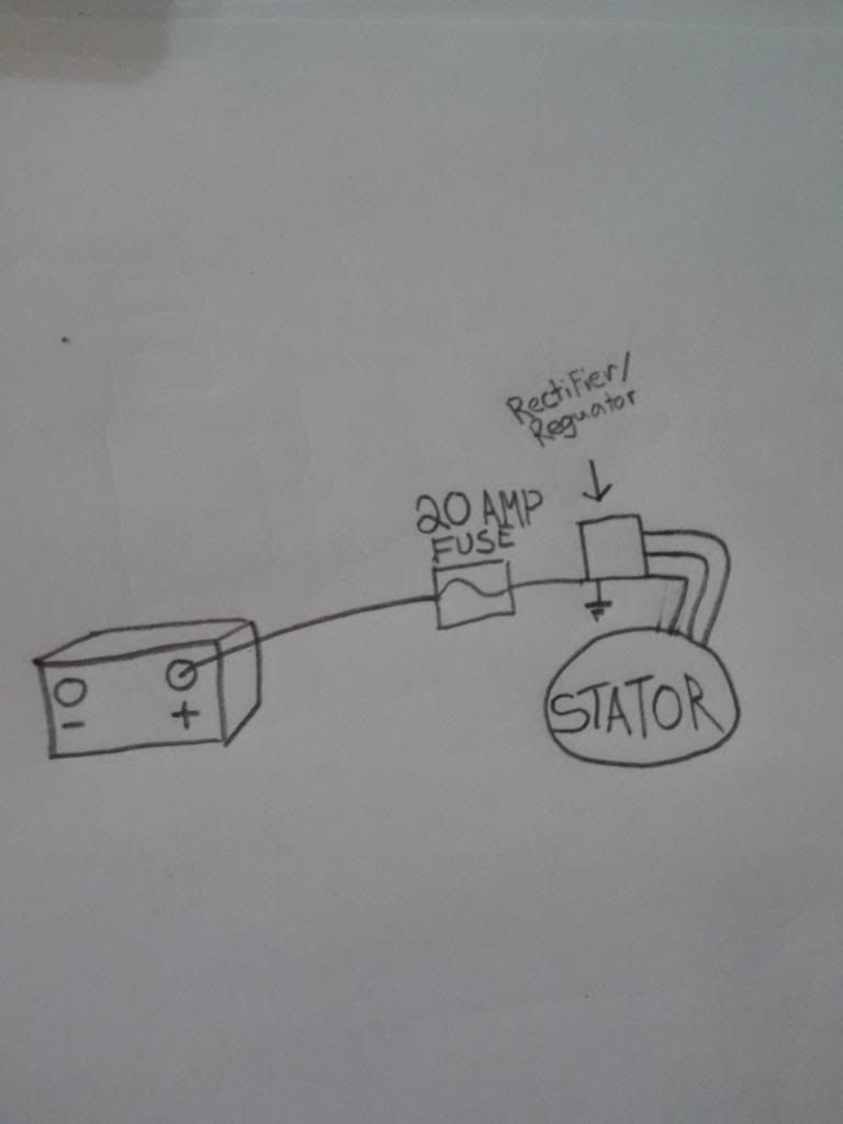
so the only way i see to hook it up is like this?
 I don't know where to go from here because there is no outlet as shown coming out of the regulator in the the first diagram..... I'm completely lost right now and could use some help.
Well the thing is, is that ether the regulator and or rectifier on my bike crapped out on me and i found something that replaces both with one unit buuuuuuuuut
as you can see there is a ground wire, three wires for the stator and a power wire.
so the only way i see to hook it up is like this?
1978 kz1000 Bobber
2006 MazdaSpeed6
2006 MazdaSpeed6
Please Log in or Create an account to join the conversation.
- Old Man Rock
-
- Offline
- User
-
Registered
- Posts: 6074
- Thanks: 225
Re: my kz1000 wiring situation
14 Nov 2012 08:18 - 14 Nov 2012 20:44
Your frame/engine cases should be at the same potential as battery ground. Confirm with ohm meter from bare metal frame to battery (-), should display meter deviation ! .2 - .4 ohms thus continuity (same potential).
Ground black wire to frame bolt hole w/ crimped/soldered ring connector.
NOTE: Insure frame is bare metal for optimal electrical contact.
Or terminate black conductor directly to battery (-)... If not long enough, solder w/heat shrink extension black AWG 16-18 conductor with ring terminal to battery post.
1976 KZ900-A4
MTC 1075cc.
Camshafts: Kawi GPZ-1100 .375 lift
Head: P&P via Larry Cavanaugh
ZX636 suspension
MIKUNI, RS-34'S...
Kerker 4-1, 1.5" comp baffle.
Dyna-S E.I.
Earls 10 row Oil Cooler
Acewell 2802 Series Speedo/Tach
Innovate LC1 Wideband 02 AFR meter
Phoenix, Az
MTC 1075cc.
Camshafts: Kawi GPZ-1100 .375 lift
Head: P&P via Larry Cavanaugh
ZX636 suspension
MIKUNI, RS-34'S...
Kerker 4-1, 1.5" comp baffle.
Dyna-S E.I.
Earls 10 row Oil Cooler
Acewell 2802 Series Speedo/Tach
Innovate LC1 Wideband 02 AFR meter
Phoenix, Az
Last edit: 14 Nov 2012 20:44 by Old Man Rock.
Please Log in or Create an account to join the conversation.
- Ogcoda
-
Topic Author
- Offline
- User
-
Registered
- Killing Everything
- Posts: 49
- Thanks: 0
Re: my kz1000 wiring situation
14 Nov 2012 17:22Old Man Rock wrote: Your frame/engine cases should be at the same potential as battery ground. COnfirm with ohm meter from bare meatl frame to battery (-), should display meter deviation ! .2 - .4 ohms thus continuity (same potential).
Ground black wire to frame bol hole w/ crimped/soldered ring connector.
NOTE: Insure frame is bare metal for optimal electrical contact.
Or terminate black conductor directly to battery (-)... If not long enough, solder w/heat shrink extension black AWG 16-18 conductor with ring terminal to battery post.
I'm not having troubles with the ground wires. I need to know if running power straight to the r/r then connecting the stator to that is going to complete the charging system. Because it is down different in the first picture
1978 kz1000 Bobber
2006 MazdaSpeed6
2006 MazdaSpeed6
Please Log in or Create an account to join the conversation.
- Old Man Rock
-
- Offline
- User
-
Registered
- Posts: 6074
- Thanks: 225
Re: my kz1000 wiring situation
14 Nov 2012 19:47
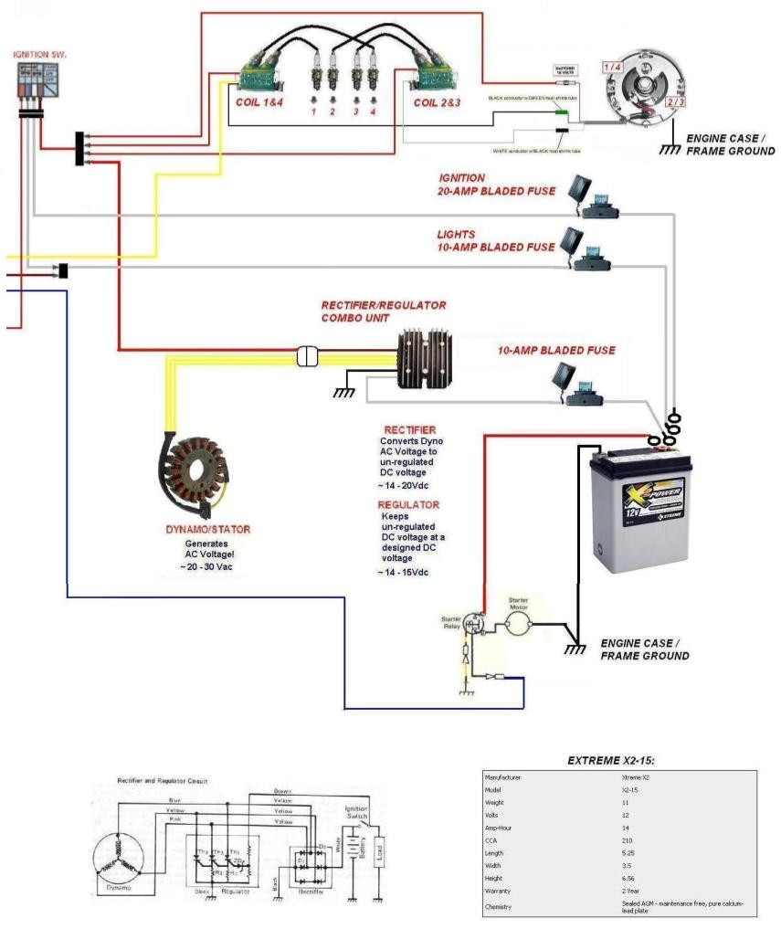
Here's my "Charging ckt" of my wiring harness I fabbed in the lattest rebuild...
1976 KZ900-A4
MTC 1075cc.
Camshafts: Kawi GPZ-1100 .375 lift
Head: P&P via Larry Cavanaugh
ZX636 suspension
MIKUNI, RS-34'S...
Kerker 4-1, 1.5" comp baffle.
Dyna-S E.I.
Earls 10 row Oil Cooler
Acewell 2802 Series Speedo/Tach
Innovate LC1 Wideband 02 AFR meter
Phoenix, Az
MTC 1075cc.
Camshafts: Kawi GPZ-1100 .375 lift
Head: P&P via Larry Cavanaugh
ZX636 suspension
MIKUNI, RS-34'S...
Kerker 4-1, 1.5" comp baffle.
Dyna-S E.I.
Earls 10 row Oil Cooler
Acewell 2802 Series Speedo/Tach
Innovate LC1 Wideband 02 AFR meter
Phoenix, Az
Attachments:
Please Log in or Create an account to join the conversation.
- 4TheKZ1000
-

- User
-
Public
- Thanks: 0
Re: my kz1000 wiring situation
14 Nov 2012 20:10 - 14 Nov 2012 20:11
I bought mine from Z1-E....it had the factory plug on it. The plug could be inserted into the factory 4 socket harness junction without any issues.
Should'nt your red wire goto the starter selinold where the red batt wire is connected ???
Should'nt your red wire goto the starter selinold where the red batt wire is connected ???
Last edit: 14 Nov 2012 20:11 by 4TheKZ1000.
Please Log in or Create an account to join the conversation.
- Old Man Rock
-
- Offline
- User
-
Registered
- Posts: 6074
- Thanks: 225
Re: my kz1000 wiring situation
14 Nov 2012 20:42 - 14 Nov 2012 20:47
nope...
In following the OEM wiring diagram for seperate Rect/Reg, (KZ900 in my case) the white conductor is connected to battery (+) while red conductor (Brown) is fed to ignition switch.
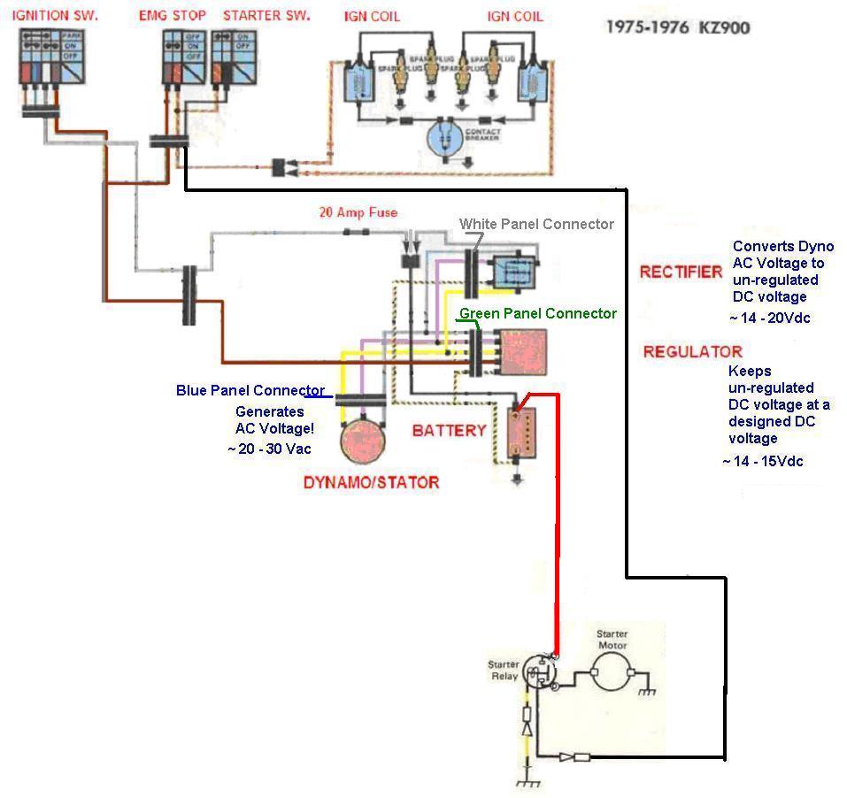
In case needed...
In following the OEM wiring diagram for seperate Rect/Reg, (KZ900 in my case) the white conductor is connected to battery (+) while red conductor (Brown) is fed to ignition switch.
In case needed...
1976 KZ900-A4
MTC 1075cc.
Camshafts: Kawi GPZ-1100 .375 lift
Head: P&P via Larry Cavanaugh
ZX636 suspension
MIKUNI, RS-34'S...
Kerker 4-1, 1.5" comp baffle.
Dyna-S E.I.
Earls 10 row Oil Cooler
Acewell 2802 Series Speedo/Tach
Innovate LC1 Wideband 02 AFR meter
Phoenix, Az
MTC 1075cc.
Camshafts: Kawi GPZ-1100 .375 lift
Head: P&P via Larry Cavanaugh
ZX636 suspension
MIKUNI, RS-34'S...
Kerker 4-1, 1.5" comp baffle.
Dyna-S E.I.
Earls 10 row Oil Cooler
Acewell 2802 Series Speedo/Tach
Innovate LC1 Wideband 02 AFR meter
Phoenix, Az
Attachments:
Last edit: 14 Nov 2012 20:47 by Old Man Rock.
Please Log in or Create an account to join the conversation.
- Ogcoda
-
Topic Author
- Offline
- User
-
Registered
- Killing Everything
- Posts: 49
- Thanks: 0
Re: my kz1000 wiring situation
14 Nov 2012 21:46Old Man Rock wrote: nope...
In following the OEM wiring diagram for seperate Rect/Reg, (KZ900 in my case) the white conductor is connected to battery (+) while red conductor (Brown) is fed to ignition switch.
In case needed...
I understand what your saying but the only thing i can't figure out is that the R/R that i posted a picture of only has 5 wires. You're diagram cleared allot up but your R/R has 6 wires.... Do i have the wrong one?
1978 kz1000 Bobber
2006 MazdaSpeed6
2006 MazdaSpeed6
Please Log in or Create an account to join the conversation.
- Ogcoda
-
Topic Author
- Offline
- User
-
Registered
- Killing Everything
- Posts: 49
- Thanks: 0
Re: my kz1000 wiring situation
14 Nov 2012 23:33
From your diagram (Old Man Rock) it looks to me like the Stator, and R/R are constantly getting power even if the key is shut off...... I'm REALLY confused wouldn't this cause your battery to die? The power looks like it goes from the battery then is fused then goes to the R/R and stator then comes out and into the ign switch....
1978 kz1000 Bobber
2006 MazdaSpeed6
2006 MazdaSpeed6
Please Log in or Create an account to join the conversation.
- Old Man Rock
-
- Offline
- User
-
Registered
- Posts: 6074
- Thanks: 225
Re: my kz1000 wiring situation
15 Nov 2012 08:31 - 16 Nov 2012 07:47
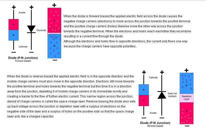
With out going into deep electrical theory, think of a diodes operation in regards to DC voltage & currents as a one way current valve. ")
The single thin line on the tip of the triangle is the Cathode (-), the flat triangle end is the Anode (+). Since the positive +Vdc (Baterry) voltage is terminated to the cathode (-) thus "reversed bias", current is blocked through the diodes depletion zone (valves 3 phase rectifier diodes) thus isn't draining the battery in this configuration.
If the diodes were reversed where the battery voltage was connected to the anodes (+) then your thoughts would be correct where the battery would be continuosly draining.
Easiet way I can put it... Hope this helped,
OMR
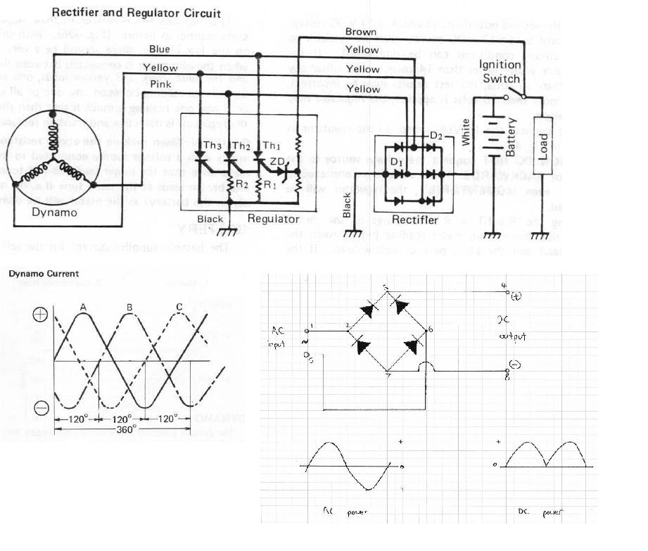
I put a little electrical theory on the forum, maybe this will provide a better understanding of the KZ eletrical system...
kzrider.com/filebase/doc_download/463-kz900-electrical-theory
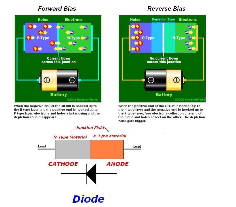
The single thin line on the tip of the triangle is the Cathode (-), the flat triangle end is the Anode (+). Since the positive +Vdc (Baterry) voltage is terminated to the cathode (-) thus "reversed bias", current is blocked through the diodes depletion zone (valves 3 phase rectifier diodes) thus isn't draining the battery in this configuration.
If the diodes were reversed where the battery voltage was connected to the anodes (+) then your thoughts would be correct where the battery would be continuosly draining.
Easiet way I can put it... Hope this helped,
OMR
I put a little electrical theory on the forum, maybe this will provide a better understanding of the KZ eletrical system...
kzrider.com/filebase/doc_download/463-kz900-electrical-theory
1976 KZ900-A4
MTC 1075cc.
Camshafts: Kawi GPZ-1100 .375 lift
Head: P&P via Larry Cavanaugh
ZX636 suspension
MIKUNI, RS-34'S...
Kerker 4-1, 1.5" comp baffle.
Dyna-S E.I.
Earls 10 row Oil Cooler
Acewell 2802 Series Speedo/Tach
Innovate LC1 Wideband 02 AFR meter
Phoenix, Az
MTC 1075cc.
Camshafts: Kawi GPZ-1100 .375 lift
Head: P&P via Larry Cavanaugh
ZX636 suspension
MIKUNI, RS-34'S...
Kerker 4-1, 1.5" comp baffle.
Dyna-S E.I.
Earls 10 row Oil Cooler
Acewell 2802 Series Speedo/Tach
Innovate LC1 Wideband 02 AFR meter
Phoenix, Az
Attachments:
Last edit: 16 Nov 2012 07:47 by Old Man Rock.
Please Log in or Create an account to join the conversation.
- Old Man Rock
-
- Offline
- User
-
Registered
- Posts: 6074
- Thanks: 225
Re: my kz1000 wiring situation
16 Nov 2012 07:48
For the inquisitive minds...
1976 KZ900-A4
MTC 1075cc.
Camshafts: Kawi GPZ-1100 .375 lift
Head: P&P via Larry Cavanaugh
ZX636 suspension
MIKUNI, RS-34'S...
Kerker 4-1, 1.5" comp baffle.
Dyna-S E.I.
Earls 10 row Oil Cooler
Acewell 2802 Series Speedo/Tach
Innovate LC1 Wideband 02 AFR meter
Phoenix, Az
MTC 1075cc.
Camshafts: Kawi GPZ-1100 .375 lift
Head: P&P via Larry Cavanaugh
ZX636 suspension
MIKUNI, RS-34'S...
Kerker 4-1, 1.5" comp baffle.
Dyna-S E.I.
Earls 10 row Oil Cooler
Acewell 2802 Series Speedo/Tach
Innovate LC1 Wideband 02 AFR meter
Phoenix, Az
Attachments:
Please Log in or Create an account to join the conversation.
- loudhvx
-

- Offline
- KZr Legend
-

Registered
- Posts: 10864
- Thanks: 1619
Re: my kz1000 wiring situation
16 Nov 2012 12:28 - 16 Nov 2012 12:38
The 6th wire (brown wire on KZ reg/recs) does not supply power. It just senses battery voltage. They put it on the switched power side of the circuit so it won't drain the battery.
Different designs for the regulator allow the reg to use the output wire to sense the battery voltage, thus eliminating the 6th wire. Some KZ650's use this type. However, sometimes they were problematic, apparently, since Kaw went back to the 6-wire type with the brown sense wire.
Aftermarket reg/recs may still use the 5-wire type, where there is no dedicated sense line. That is likely what you have.
In that case you wire it like this:
BTW, as it is shown, that diagram is not complete. The reulator may not work properly until the battery is grounded. (I assume it is grounded in real life, just not on the diagram.)
1981 KZ550 D1 gpz.
Kz550 valve train warning.
Other links.
Kz550 valve train warning.
Other links.
Attachments:
Last edit: 16 Nov 2012 12:38 by loudhvx.
Please Log in or Create an account to join the conversation.
Moderators: Street Fighter LTD