
82 GPZ B2 - No electrical power after restore.
- Hollywoodmx
-
 Topic Author
- Offline
- User
-

Registered
- Posts: 562
- Thanks: 16
82 GPZ B2 - No electrical power after restore.
23 Apr 2012 22:43 - 23 Apr 2012 22:46
I charged the battery and tested 12.7V so shes ready, fuses look good but I turn on the key switch and nada, no power to anything, no lights, no console, no fuel pump, etc.
Perhaps I'm a dummy and I forgot to plug something in..??
I did notice I have no power across each fuse which doesn't sound right...Th main fuse connector I never touched.
Any help would be appreciated. Also any wiring diagrams around the air temp sensor would be appreciated..several wires there not connected without any obvious wire color matches and connector matches.
As far as what I took apart;
All the console and headlight and hand controls, signal lights, all 3 airboxes (lol), throttle bodies, gas tank,brakes, rear wheel, chain, engine case covers both sides.
- 82 GPz1100injection
- 77 Kz1075 Supercharged
- 81 Yamaha TR-1
- 81 Yamaha xv920
Calgary
- 77 Kz1075 Supercharged
- 81 Yamaha TR-1
- 81 Yamaha xv920
Calgary
Last edit: 23 Apr 2012 22:46 by Hollywoodmx.
Please Log in or Create an account to join the conversation.
- Motor Head
-
- Offline
- User
-
Registered
- FIX UP YOUR BIKE RIGHT AND CHEAP
- Posts: 5137
- Thanks: 393
Re: 82 GPZ B2 - No electrical power after restore.
23 Apr 2012 23:20
will one of the wiring diagrams in File Base help?
www.kzrider.com/filebase/cat_view/102-19...-kawasaki-kz-1000-r1
Do you have power coming into the Fuse Panel at the Main Fuse? Red/ white wire plugged in from Battery cable to fuse panel? Maybe a blown or not connecting Main Fuse.
www.kzrider.com/filebase/cat_view/102-19...-kawasaki-kz-1000-r1
Do you have power coming into the Fuse Panel at the Main Fuse? Red/ white wire plugged in from Battery cable to fuse panel? Maybe a blown or not connecting Main Fuse.
1982 KZ1000LTD K2 Vance & Hines 4-1 ACCEL COILS Added Vetter fairing & Bags. FOX Racing rear Shocks, Braced Swing-arm, Fork Brace, Progressive Fork Springs RT Gold Emulators, APE Valve Springs, 1166 Big Bore kit, RS34's, GPZ cams.
1980 KZ550LTD C1 Stock SOLD Miss it
1979 MAZDA RX7 in the works, 13B...
1980 KZ550LTD C1 Stock SOLD Miss it
1979 MAZDA RX7 in the works, 13B...
Please Log in or Create an account to join the conversation.
- MFolks
-

- Offline
- User
-
Registered
- Posts: 6650
- Thanks: 541
Re: 82 GPZ B2 - No electrical power after restore.
23 Apr 2012 23:26
Do you have a multimeter for seeing where the voltage is and isn't? The first place I'd check is the plug/connector under the fuel tank. I believe there is a 9 pin connector that goes to the main fuse block mounted on the air filter box.
You'll need the meter set on VDC(Volts,Direct Current) range of 20, put the Black probe on the negative(-) battery post/terminal, and the Red probe on any of the fuses.
You'll need the meter set on VDC(Volts,Direct Current) range of 20, put the Black probe on the negative(-) battery post/terminal, and the Red probe on any of the fuses.
1982 GPZ1100 B2
General Dynamics/Convair 1983-1993
GLCM BGM-109 Tomahawk, AGM-129A Advanced Cruise Missile (ACM)
General Dynamics/Convair 1983-1993
GLCM BGM-109 Tomahawk, AGM-129A Advanced Cruise Missile (ACM)
Please Log in or Create an account to join the conversation.
- Patton
-

- Offline
- KZr Legend
-

Registered
- Posts: 18568
- Thanks: 2102
Re: 82 GPZ B2 - No electrical power after restore.
24 Apr 2012 00:09
Link to wiring diagram for 1982 KZ1100-B2 (GPZ):
Click > www.kzrider.com/filebase/doc_download/263-kz1100b2
This isn't the exact same diagram, but gives a good idea of the voltage check-points.
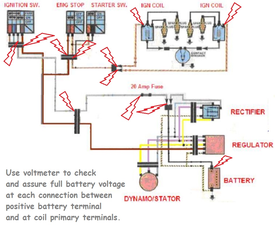
If not already done, would assure integrity of the ground connection where the negative battery cable attaches to rear of the engine.
Good Fortune!")
Click > www.kzrider.com/filebase/doc_download/263-kz1100b2
This isn't the exact same diagram, but gives a good idea of the voltage check-points.
If not already done, would assure integrity of the ground connection where the negative battery cable attaches to rear of the engine.
Good Fortune!
1973 Z1
KZ900 LTD
KZ900 LTD
Attachments:
Please Log in or Create an account to join the conversation.
- Hollywoodmx
-
Topic Author
- Offline
- User
-
Registered
- Posts: 562
- Thanks: 16
Re: 82 GPZ B2 - No electrical power after restore.
24 Apr 2012 01:11MFolks wrote: Do you have a multimeter for seeing where the voltage is and isn't? The first place I'd check is the plug/connector under the fuel tank. I believe there is a 9 pin connector that goes to the main fuse block mounted on the air filter box.
You'll need the meter set on VDC(Volts,Direct Current) range of 20, put the Black probe on the negative(-) battery post/terminal, and the Red probe on any of the fuses.
Thanks man. Ya I have a volt meter. I got power now was the red whites needed to join. This is my status now;
What I have:
- Rear right signal
- Rear brake
- fuel pump
- console
- head light
- horn
- she runs too!
- all fuses check out
What I dont have:
- Front signals
- rear left signal (bad bulb I think)
- front brake (lighting)
Going to post a video for you.
- 82 GPz1100injection
- 77 Kz1075 Supercharged
- 81 Yamaha TR-1
- 81 Yamaha xv920
Calgary
- 77 Kz1075 Supercharged
- 81 Yamaha TR-1
- 81 Yamaha xv920
Calgary
Please Log in or Create an account to join the conversation.
- Hollywoodmx
-
Topic Author
- Offline
- User
-
Registered
- Posts: 562
- Thanks: 16
Re: 82 GPZ B2 - No electrical power after restore.
24 Apr 2012 01:32 - 24 Apr 2012 01:39Patton wrote: Link to wiring diagram for 1982 KZ1100-B2 (GPZ):
Click > www.kzrider.com/filebase/doc_download/263-kz1100b2
This isn't the exact same diagram, but gives a good idea of the voltage check-points.
If not already done, would assure integrity of the ground connection where the negative battery cable attaches to rear of the engine.
Good Fortune!
Nice! Thanks, I have a service manual on its way but this is helful for sure. That drawing will help me get my blinkers going for sure. Now I just need you guys to have a look at the airbox just to make sure any of the un plugged wires need to be plugged into something..lol.
Here is a video I made with my issues, hoping that will help.
- 82 GPz1100injection
- 77 Kz1075 Supercharged
- 81 Yamaha TR-1
- 81 Yamaha xv920
Calgary
- 77 Kz1075 Supercharged
- 81 Yamaha TR-1
- 81 Yamaha xv920
Calgary
Last edit: 24 Apr 2012 01:39 by Hollywoodmx.
Please Log in or Create an account to join the conversation.
- MFolks
-
- Offline
- User
-
Registered
- Posts: 6650
- Thanks: 541
Re: 82 GPZ B2 - No electrical power after restore.
24 Apr 2012 01:57
Does the FI still work? If so, you'll need to connect the TPS(throttle position sensor),the engine temperature sensor(between #1 and #2 cylinder on the intake side), and the air temperature sensor(it's in front of where the fuse block mounts).
Kawasaki Fuel Injection Sensor Specs
Here's from my 1982 GPz1100 B2 factory shop manual:
Air temperature sensor spec(probably the one on the air filter housing, or next to it).
Meter at ohms X 1K ohms ( I use ohms X 2K as it works on my meter)
Disconnect the wiring from the harness, one meter probe to one of the connector pins, the other on the last pin.
Should read 2.0K ohms to 3.0 K ohms at 68 F, if your meter won't read this, try the 20K ohm setting.
A footnote says this reading is true when sensor temperature is 20C (68F), 4.7 K ohms to 7.6 K ohms when 0 C (32 F) and 1.4 K ohms to 2.2 K ohms when 30 C (86 F).
Engine temperature sensor spec:
Again, meter to 2K ohm settings, one meter lead to the push on terminal (remove the wire as it may give a false reading) and the other to a chassis ground(any Black with Yellow stripe wire is part of the ground circuit).
The readings will be the same as the air temperature sensor.
The TPS has an electrical connector, only the first three(3) contacts are used, counting from left to right as you face it.
From my factory shop manual I'm making it easier to get the readings, by using shortcuts).
1. Ignition switch off.
2. Remove the small SS clip holding the cable to the TPS.
3. Using a multimeter set on ohms, range of 2K.
4. Measure between the first electrical contact on the left and the third to the right.
5. It should read between 3.3K ohms to 6.8K ohms.
The next test will cover the range between idle and full throttle:
1. Set the meter's probes on the left contact and the one next to it, as this is the idle position check.
2. Readings should be between 2.1K ohms to 4.2 K ohms
Full throttle check:
1. Same electrical contacts used.
2. With the throttle wide open, readings should be between 0.35 K ohms to 0.71 K ohms, see if the resistance changes smoothly, with no fluctuations or wide variations as the throttle is closed down to the idle position.
3. If there are variations, try cleaning the TPS with the De-Oxit electrical contact cleaner/preservative. Open and close it with the throttle while spraying the cleaner up inside.
4. www.deoxit.com is the website for the electrical contact cleaner/preservative. It can be purchased at Radio Shack Stores and other electronic supply places.
1982 GPZ1100 B2
General Dynamics/Convair 1983-1993
GLCM BGM-109 Tomahawk, AGM-129A Advanced Cruise Missile (ACM)
General Dynamics/Convair 1983-1993
GLCM BGM-109 Tomahawk, AGM-129A Advanced Cruise Missile (ACM)
Please Log in or Create an account to join the conversation.
- MFolks
-
- Offline
- User
-
Registered
- Posts: 6650
- Thanks: 541
Re: 82 GPZ B2 - No electrical power after restore.
24 Apr 2012 02:01
Color Codes On Most Kawasaki’s (written for 1980’s bikes)
HEADLIGHT
RED with BLACK stripe, High Beam.
RED with YELLOW stripe, Low Beam.
BLACK with YELLOW stripe, the ground circuit.
BRAKE/TAIL LIGHT Can be an # 1157 dual filament bulb
RED, Running or Tail Light.
BLUE,(sometimes with a Red stripe) Brake Light Circuit.
BLACK with YELLOW stripe, the ground circuit.
LEFT FRONT TURN SIGNAL Can be an #1157 dual filament bulb
GREEN, Left front turn signal circuit.
BLUE, Left front running light circuit.
BLACK with YELLOW stripe, the ground circuit.
RIGHT FRONT TURN SIGNAL Can be an # 1157 dual filament bulb
GREY, Right front turn signal circuit.
BLUE, Right front running light circuit.
BLACK with YELLOW stripe, the ground circuit.
LEFT REAR TURN SIGNAL Can be an #1156 single filament bulb
GREEN, Left rear turn signal circuit.
BLACK with YELLOW stripe, the ground circuit.
RIGHT REAR TURN SIGNAL Can be an #1156 single filament bulb
GREY, Right rear turn signal circuit.
BLACK with YELLOW stripe, the ground circuit.
I'd open up the headlight housing, looking for loose/correded connectors. The front running lights are powered by BLUE wires.
1982 GPZ1100 B2
General Dynamics/Convair 1983-1993
GLCM BGM-109 Tomahawk, AGM-129A Advanced Cruise Missile (ACM)
General Dynamics/Convair 1983-1993
GLCM BGM-109 Tomahawk, AGM-129A Advanced Cruise Missile (ACM)
Please Log in or Create an account to join the conversation.
- Hollywoodmx
-
Topic Author
- Offline
- User
-
Registered
- Posts: 562
- Thanks: 16
Re: 82 GPZ B2 - No electrical power after restore.
24 Apr 2012 02:15 - 24 Apr 2012 03:15
Im working on the signal lights. (edit, signal lights working).
The FI seems to work, it worked before the build too, but my temp sensor wiring is a bit different because I have a variable resistor for the air sensor.
*Edit, I think the white black in the video is meant for the pink wire with the orange adapter.. Looking at the wiring drawing there is only one white black and it joins a pink.. I think.
- 82 GPz1100injection
- 77 Kz1075 Supercharged
- 81 Yamaha TR-1
- 81 Yamaha xv920
Calgary
- 77 Kz1075 Supercharged
- 81 Yamaha TR-1
- 81 Yamaha xv920
Calgary
Last edit: 24 Apr 2012 03:15 by Hollywoodmx.
Please Log in or Create an account to join the conversation.
- tito
-

- Offline
- User
-
Registered
- Posts: 17
- Thanks: 3
Re: 82 GPZ B2 - No electrical power after restore.
26 Apr 2012 16:49
GPZ1100 manual can be downloaded from this link
www.kawiworld.com/index.php?option=com_c...icle&id=77&Itemid=99
Wire diagram can be found from the "filebase" on this site.
kzrider.com/filebase/cat_view/102-1982/194-kawasaki-kz-1100-b2
The pink wire is for battery level sensor, since battery sensor is not anymore available, you can disable the indicator by connecting the pink wire to + terminal.
Please Log in or Create an account to join the conversation.
- MFolks
-
- Offline
- User
-
Registered
- Posts: 6650
- Thanks: 541
Re: 82 GPZ B2 - No electrical power after restore.
26 Apr 2012 19:07
1982 Kawasaki GPZ1100 B2 ECU Pin out
I got out my well used service manual and copied the wire pin-out if you are going to use the EFI system.
The connector is numbered left to right with pin #1 on the lower row of pins
with #12 above #1 .
I'll give you the pin-out and wire colors that are viewed from the wire side.
#1 Black/Yellow Ground
#2 Blank
#3 Blank
#4 White/Red Battery +
#5 Blue/Red Sensor Ground
#6 Blue Air Temperature Sensor +
#7 Blue/Yellow Control Unit +
#8 Green Engine Speed
#9 Blank
#10 Gray Engine Temperature +
#11 Blue/White Throttle Opening Angle
#12 Yellow Injector Drive Signal
#13 Blank
#14 Blank
#15 Blank
#16 Black/Green Control Unit Ground
#17 Blue/Orange Throttle Sensor +
#18 Black Engine Speed
#19 Red/Black Starter Signal
#20 Blank
#21 Green/White Fuel Pump Relay Drive Signal
If your fuel pump or fuel pressure regulator is going out, here's some choices:
Fuel Pumps & Regulators
www.fuel-pumps.net/gsl393.html
www.mpsracing.com/products/MPS/FuelPumps.asp
www.airtexproducts.com/
And fuel injector servicing:
www.witchhunter.com
www.injectorrx.com/services.html
www.injector-rehab.com/
1982 GPZ1100 B2
General Dynamics/Convair 1983-1993
GLCM BGM-109 Tomahawk, AGM-129A Advanced Cruise Missile (ACM)
General Dynamics/Convair 1983-1993
GLCM BGM-109 Tomahawk, AGM-129A Advanced Cruise Missile (ACM)
Please Log in or Create an account to join the conversation.
- Hollywoodmx
-
Topic Author
- Offline
- User
-
Registered
- Posts: 562
- Thanks: 16
Re: 82 GPZ B2 - No electrical power after restore.
26 Apr 2012 21:53
Ok. So I got it all to work in the end.
At the air box I connected the pink to the white black. So far so good.
I had two problems. One I broke the small connector on my potentiomer which I fixed. Second was I was having wierd idleing issues, turned out I tightend my hand throttle case too tight affecting the throttle cable.
As far as the signal lights, weird but I ended up not connecting the blue & green wires, just the grey and the grounds (black/yellow). If I connect the all the 3 blues and the one green one of the front signal stays on. Blues must be for hazards or something which didnt work on my bike anyways.
One thing I forgot was how loud and bad ass my exhaust sounds, its a cross between a muscle sound and jap super bike sound. I have the baffle but I'm thinking it's worn out..lol.
- 82 GPz1100injection
- 77 Kz1075 Supercharged
- 81 Yamaha TR-1
- 81 Yamaha xv920
Calgary
- 77 Kz1075 Supercharged
- 81 Yamaha TR-1
- 81 Yamaha xv920
Calgary
Please Log in or Create an account to join the conversation.
Moderators: Street Fighter LTD