
83 1100 spectre
- garyprather
-
 Topic Author
- Offline
- User
-

Registered
- Posts: 133
- Thanks: 0
83 1100 spectre
08 Apr 2012 21:46
I am hoping someone here can help me out here. I pulled my engine to paint it. It is now back in and all together but I have obtained a very bad miss or something. I checked the coils and seem to be getting great spark. 12.5 ohm on both coils. I also checked the timing with a timing light. That also seems to be right on all 4 wires. I went through the grounds and such cleaned and made sure there was no paint where they go. I am getting 12 to 14 volts from my battery. Maybe I am searching in the wrong locations. Could be a carb issue but they were taken off easy and put back on the same day, no setting around or jarring. There was 3 yellow wires coming out of the generator under the left side of the engine cover. I would like to think these wire can go back in any order right??? I am open to any insight on this. The bike really does not change idle when i remove 2 and 3 plug wires. I do notice a bit of a difference but not like it was. It is really gutless at slow speeds and stalls out.
Please Log in or Create an account to join the conversation.
- MFolks
-

- Offline
- User
-
Registered
- Posts: 6650
- Thanks: 541
Re: 83 1100 spectre
08 Apr 2012 23:44
Three three (3) yellow wires do not go in any sequence as they are 120 degrees apart. But do an ohm check of the stator windings and check for voltages too:
Alternator Testing For the Older 4’s(Z1’s,Kz 900’s, Kz1000’s,Kz1100’s ,GPz1100’s
And possibly the 750’s).
To check to see if the alternator is working you need to follow these simple steps:
1. Fully charge the battery as this will be the power source during this test.
2. Disconnect the Regulator/Rectifier at the plug that has the six wires in it.
3. Start the engine and let it warm to operating temperature.
4. If you're worried about overheating, position a large fan for cooling the engine.
5. After the engine has reached operating temperature, have a helper assist you, and using a multi-meter, read the output at the three yellow wires (or the alternator output wires)at the disconnected connector.
6. Raise the engine speed to 4000 rpm, and see what the three YELLOW wire combinations(or any alternator output wires) are(1-3, 2-3 & 1-2). The output will be around 50 Volts A.C.(Alternating Current). BE CAREFUL, AS THERE IS A SHOCK HAZARD HERE!!
7. If any of the combinations are low or non-existent, the stator(wire windings) are bad and must be replaced. Some of the older Z1’s and KZ900’s were reported to be phase sensitive, so check the wire colors carefully.
8. Using an OHMETER, Check the three wire combinations again, looking for a reading of 0.36 - 0.54 OHMS. If the readings are above or below, the stator may be bad and need replacement. Also check from any of the three YELLOW wires to ground, this will show if arcing took place. Check only with the engine off !!
9. Before ordering a new stator, check the connections from the stator as there are electrical "Bullet" connectors that may be damaged or dirty. Inspect the wiring for signs of shorting or overheating too. www.z1enterprises.com sells replacement rubber grommets for the alternator output wiring, they get hard and could leak oil after a while.
10. Check the wiring coming out of the grommet as there have been situations where the wires were damaged causing a short(I.E. twisted together with insulation damage).
11. The sprocket cover will have to be removed to access the electrical connectors coming from the alternator, the left foot peg assembly and shifting lever will have to come off also.
Alternator Stator Replacement On the Older 4’s
Source for replacement Stators
A. www.electrosport.com/technical-resources.../fault-finding-guide
B. www.customrewind.com
C. www.rmstator.com
D. www.regulatorrectifier.com
1. If by testing either by checking the output voltage from the stator or by using and ohmmeter for resistance and the stator is determined to be bad, replacing the stator is not a difficult job.
2. The motorcycle owner should have on hand a replacement alternator gasket as it will tear on removal and leak if reused.
3. Put the bike on the center stand if possible and lean it to the right to minimize the oil volume that could come out when the alternator cover is removed.
4. Have selection of Metric wrenches and sockets along with Metric Allen keys to be able to accomplish this repair. ¼" and 3/8" ratchets and extensions may be needed along with Allen bits.
5. Remove the gear shift lever, the sprocket cover and possibly the left foot peg assembly.
6. A catch pan for what little oil will be lost should be positioned under the alternator on the left side. Newspapers will soak up any oil lost or some kitty litter will do as an absorbent.
7. Remove the alternator cover fasteners, some bikes use a socket head cap screw(Allen type) and others use the Phillips head type, the #3 screwdriver bit fits best for those. Use a small dish or can to collect the removed fasteners from the parts to prevent loss/damage.
8. The alternator stator is secured to the inside of the cover usually with three Allen headed bolts, Some bikes may have Torx style fasteners, Remove them and disconnect the three yellow wires that have bullet connectors on them from the bundled wires inside the sprocket cover.
9. If your bike has some color other than yellow for the alternator output wires, make note of what goes where as the older Kawasaki’s were phase sensitive in regard to the regulator/rectifiers.
10. When installing the replacement stator, clock or position the output wires and grommet so they fit into the small port under the alternator cover without being pinched or damaged.
11. Tighten the three Allen or Torx fasteners, securing the replacement stator to the cover. I like using the BLUE Loctite # 242 for hardware that can be removed with hand tools.
12. Remove the old gasket from the mating surfaces of the alternator cover and engine case by scraping with a piece of sharpened plastic like Lexan or Plexi-glass as these will not gouge the soft Aluminum Cases. Avoid using a metal gasket scraper for this.
13. Position the alternator cover, checking for pinched wiring and install the fasteners with a little silver anti-seize on the threads, tightening to the correct torque.
14. Connect up the output wires to the mating female bullet connectors and while you’re in there, check the routing of the wire bundle that runs through there.
15. Inspect for signs of heat damage to the wire insulation and vibration damage too.
16. The side stand switch, neutral switch, and oil pressure switch wiring are all bundled with the alternator output wiring running above and behind the engine output sprocket. This bundle runs in a channel as it goes up toward the various electrical connections.
17. The regulator/rectifier plug on the 80’s bikes usually has six wires in it:
A. One (1)WHITE with RED stripe, this is the bikes main power wire usually 12 gauge in size.
B. One(1) smaller Brown wire, probably 18 gauge or so, the voltage sense wire for the regulator/rectifier, helps keeping it from overcharging the battery.
C. One(1) BLACK with YELLOW stripe wire, part of the ground circuits, maybe 16 gauge in size.
D. Three(3) YELLOW wires, maybe 14 gauge in size, the alternator output wires going to the regulator/rectifier which converts the Alternating Current(A.C.) to Direct Current(D.C.) using rectification, producing the power to run the motorcycle and charge the battery.
18. Reinstall the sprocket cover, again checking for pinched wires before tightening. Install the shifter on it’s splined shaft checking for proper location, and the left side foot peg assembly.
19. Except for the minor oil spill and reluctant fasteners, it’s not a very difficult job to do.
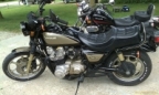
1982 GPZ1100 B2
General Dynamics/Convair 1983-1993
GLCM BGM-109 Tomahawk, AGM-129A Advanced Cruise Missile (ACM)
General Dynamics/Convair 1983-1993
GLCM BGM-109 Tomahawk, AGM-129A Advanced Cruise Missile (ACM)
Please Log in or Create an account to join the conversation.
- garyprather
-
Topic Author
- Offline
- User
-
Registered
- Posts: 133
- Thanks: 0
Re: 83 1100 spectre
10 Apr 2012 01:47
Ok I have checked the coils and wires right and left side get the same input voltage. all plugs are sparking. But I hear a clicking noise as like it my be arc jump??? Its by the coil that runs 2 and 3 cylinders. I turned off all the lights to check for a spark, but nothing was seen. # 2 and 3 exhaust pipes are a lot cooler than 1 and 4. This has become frustrating I wonder if what is wrong is a coil happen to start failing after I put the engine back on the bike or if it is a wire I am missing as in pinched corroded and such. How do i check the output voltage of the coils? I know i have spark at them but maybe its weak.
Please Log in or Create an account to join the conversation.
- MFolks
-
- Offline
- User
-
Registered
- Posts: 6650
- Thanks: 541
Re: 83 1100 spectre
10 Apr 2012 01:56
Check the input voltage, depending on how strong the battery is, and what other current drawing circuits are energized, it should be close to battery voltage(if it's down to 8 volts or so, you've got a voltage drop).
Checked the sparkplug caps? they should ohm check to 5000 ohms, and unscrew from the sparkplug wires.
Cleaning Motorcycle Electrics
Get some of the De-Oxit electrical contact cleaner and figure on spending a good day going from the front of the bike to the back. It’s a plastic safe cleaner/preservative. www.deoxit.com is their website. Or use any plastic safe electrical contact cleaner(NOT WD-40 !).
On the older Kawasaki's, a majority of electrical connectors are inside the headlight housing requiring removal of the headlight, then the fun begins.
Do one set of electrical connectors at a time to avoid mixing up what connects to where. Usually disconnecting, spraying with De-Oxit and reconnecting is about all you'll need.
However, when encountering the green crud of corrosion, a brass wire brush may be needed on the pins you can reach.
Some 400-600 grit wet and dry sandpaper strips rolled into a tube should reach the male and female pins in the more difficult to clean connectors.
Smoker’s pipe cleaners, cotton swabs and wooden toothpicks work as cleaning aids.
Really small electrical connectors may require the use of a welders tip cleaning tool assortment.
Most pins in the connectors are coated with a thin plating of tin, and others may be nothing more than copper or brass.
If moisture is added, the resulting corrosion lowers the voltage/current being carried causing dim lights, slow engine cranking, slow turn signal responce and lower input voltage to the ignition coils resulting in weak spark.
The left and right handlebar switch pods will need attention too as they have circuit functions like turn, horn, run/stop, and start. The older Kawasaki’s have reports of the soldered connections crumbling, if your bike has this problem, just ask, as I’ve got a repair procedure for this.
Usually a spritz or two with actuation of the switch is about all needed for these switches unless corrosion is detected and then careful disassembly is required.
The ignition switch may or may be not sealed to allow spraying the internal contacts. I urge caution if attempting to open this up as springs, and ball bearings may fly out never to be seen again!
If your bike has the older style glass tubed fuses, I suggest replacing them as vibration can cause internal failure. AGX is the type used, and most auto parts stores can get them for you.
Clean the fuse holder clips, looking for signs of overheating(discolored insulation, signs of melting). I use metal polish on a cotton swab, followed by spraying another clean swab with the De-Oxit and then rubbing the inside of the fuse clip.
All battery cables must be clean and tight for maximum current transfer. Check the cables going from the Negative(-) battery terminal/post to the engine mounting bolt
Also the one going from the Positive(+) terminal to the starter solenoid and from there to the starter motor.
If any battery cable feels ”Crunchy” when flexed, replace it as possible corrosion is inside the insulation.
Each "Bullet Connector" will have to be sprayed to ensure good connectivity, especially the ones going to the energizing coil of the starter solenoid.
The alternator output “Bullet Connectors” are usually behind the engine sprocket cover and will need inspecting and cleaning too.
The turn signal light sockets will benefit from a spritz from the contact cleaner along with the tail light/brake light socket.
Some brake light switches can be sprayed on the actuating rod, with the spray running down inside to the electrical contacts, others may be sealed requiring replacement if the switch is intermittent in operation.
Some people put the Di-Electric Grease on cleaned terminations/connectors, I don’t, as I’ve read/heard it can cause problems when it gets hot, actually insulating the connections, so the choice is yours to use or not.
I think I've covered about all of the electrical systems on the bike.........
“I spent a weekend going through every electrical connection and switch on the bike with a little scotchbrite pad and DeOxit - what a difference! Everything was brighter, gauge backlights, indicator lights, turn signals, I was getting a nicer spark, it fired up quicker, etc. Well worth my time. WELL worth it! “
From a forum member at www.kzrider.com
1982 GPZ1100 B2
General Dynamics/Convair 1983-1993
GLCM BGM-109 Tomahawk, AGM-129A Advanced Cruise Missile (ACM)
General Dynamics/Convair 1983-1993
GLCM BGM-109 Tomahawk, AGM-129A Advanced Cruise Missile (ACM)
Please Log in or Create an account to join the conversation.
- MFolks
-
- Offline
- User
-
Registered
- Posts: 6650
- Thanks: 541
Re: 83 1100 spectre
10 Apr 2012 02:00
Testing Kawasaki Ignition Coils For Input Voltage
When voltage testing Kawasaki Ignition Coils, the following needs to be done:
1. Remove the fuel/gas tank to access the coils.
2. Fully charge the battery.
3. Using a multimeter, set it up for VDC(Volts, Direct Current), range of 20.
4. Turn on the ignition switch and the run/stop switch to “Run”.
5. Put the multimeter’s RED probe on where the red or red/yellow wire goes on the ignition coil.
6. Put the multimeter’s BLACK probe on either the battery Negative(-) post/terminal or a good frame ground.
7. You should be able to see battery voltage at the ignition coil connection, but this depends on the current draw of other items in the same circuit.
8. If the tested voltage is down to 8-9 volts, you probably need to clean the many and various electrical connectors.
1982 GPZ1100 B2
General Dynamics/Convair 1983-1993
GLCM BGM-109 Tomahawk, AGM-129A Advanced Cruise Missile (ACM)
General Dynamics/Convair 1983-1993
GLCM BGM-109 Tomahawk, AGM-129A Advanced Cruise Missile (ACM)
The following user(s) said Thank You: garyprather
Please Log in or Create an account to join the conversation.
- Patton
-

- Offline
- KZr Legend
-

Registered
- Posts: 18568
- Thanks: 2102
Re: 83 1100 spectre
10 Apr 2012 08:11With the plugs removed and grounded against the engine head, are fat blue sparks seen on every plug while spinning over the engine?garyprather wrote: ... all plugs are sparking....
Good Fortune!
")
1973 Z1
KZ900 LTD
KZ900 LTD
Please Log in or Create an account to join the conversation.
- Patton
-
- Offline
- KZr Legend
-
Registered
- Posts: 18568
- Thanks: 2102
Re: 83 1100 spectre
10 Apr 2012 08:19High intensity voltage leaking through plug wire and shorting to the engine head doesn't necessarily produce a visible spark at the source of the leakage.garyprather wrote: ...I hear a clicking noise as like it my be arc jump??? Its by the coil that runs 2 and 3 cylinders. I turned off all the lights to check for a spark, but nothing was seen. # 2 and 3 exhaust pipes are a lot cooler than 1 and 4....
Could experiment by temporarily placing some insulating material of some kind between the plug wires and engine head, to assure that the plug wires aren't touching the head.
Are the original stock coils and plug wires still being used?
Plug wires get hard and cracked with old age.
Good Fortune!
1973 Z1
KZ900 LTD
KZ900 LTD
The following user(s) said Thank You: garyprather
Please Log in or Create an account to join the conversation.
- garyprather
-
Topic Author
- Offline
- User
-
Registered
- Posts: 133
- Thanks: 0
Re: 83 1100 spectre
10 Apr 2012 11:19
Thanks everyone for the help I did check the input voltage and all is good. both coils are getting the same. I also checked the wire resistant which also was ok. I am going to try the tip patton gave using a type of insulator to see if it makes it any better. One more thing I looked through the manual and its showing the red wire to the coil is placed on the top connector because of the polarity. Mine are set up the opposite red wires on bottom green and black on top. Is this wrong?
Please Log in or Create an account to join the conversation.
- garyprather
-
Topic Author
- Offline
- User
-
Registered
- Posts: 133
- Thanks: 0
Re: 83 1100 spectre
10 Apr 2012 12:36
I just swapped the right with the left and left with the right. Still runs the same way. My #2 and #3 pipes are not hot at all. I know theres spark Because i grounded out the plugs on the engine and can see it. I am at a loss here. Has to be something I am overlooking here. What could cause this. Maybe its the carbs.
Please Log in or Create an account to join the conversation.
- garyprather
-
Topic Author
- Offline
- User
-
Registered
- Posts: 133
- Thanks: 0
Re: 83 1100 spectre
10 Apr 2012 14:51
I decided to dig into the carbs and and I reset the float height to 20mm. Now the other pipes are getting warm. I still have a clicking noise though. At idle I can not hear it but just slightly hitting the gas I can hear hit. It sounds as if it speeds up with the engine. I have to re sync the carbs now. So I am hoping that the noise is because carbs are unsynced. I am running a bit lean on the lower end tach drops slower than it did before. I will be whiching to the carb forum now thanks to everyone who helped me out.
Please Log in or Create an account to join the conversation.
Moderators: Street Fighter LTD