
Custom Loom - WHAT GAUGE CABLES?
- royalratch
-
 Topic Author
- Offline
- User
-

Registered
- Posts: 144
- Thanks: 10
Custom Loom - WHAT GAUGE CABLES?
13 Dec 2011 13:04
Calling on the sparky types here.
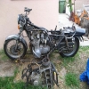
I'm going to start making a custom loom (pictured below) for my Z800 build and need to know what gauge cable to use for each part. I'm using an M-Unit to control electrics and the ring terminals are quite small on it.
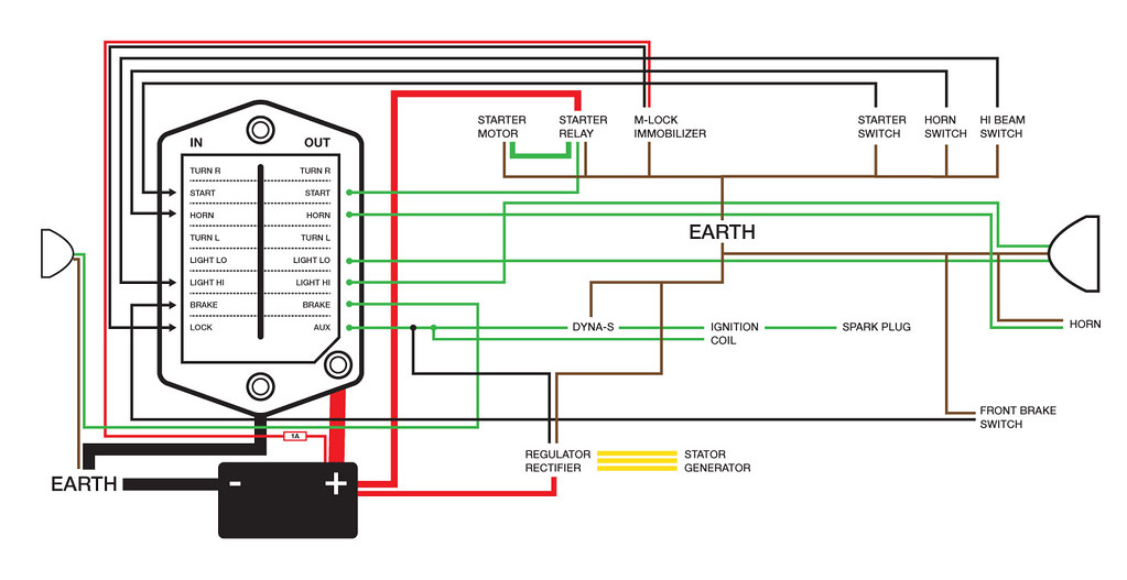
If someone could fill in the blanks as below, I'd be much obliged:
Headlamp Relay to Headlamp = 6mm / 20amp
So here is the list, grouped into sub looms:
STARTER CIRCUIT
1) Starter Switch to M-Unit =
2) Starter Switch EARTH =
3) M-Unit to Starter Relay =
4) Starter Relay to Starter Motor =
5) Battery to Starter Relay =
6) Starter Motor EARTH =
7) Starter Relay EARTH =
") M-Lock Immobiliser = SUPPLIED
M-Lock Immobiliser = SUPPLIED
9) M-Lock Immobiliser EARTH =
LIGHTS
1) Headlamp switch to M-Unit =
2) M-Unit to Headlamp =
3) Headlamp EARTH =
4) Brake Switches to M-Unit =
5) M-Unit to Brake Light =
HORN
1) Horn Switch to M-Unit =
2) M-Unit to Horn =
3) Horn EARTH =
IGNITION CIRCUIT
1) Dyna-S = INCLUDED
2) M-Unit to Coils =
3) Reg/Rect to Coils / Dyna-S =
CHARGING
1) Reg/Rect to Battery =
2) Reg/Rect to Dyna-S =
3) Reg/Rect EARTH
Also, should all earths go to the same point on the frame or should I spread them out to shorten cable runs?
Many thanks in advance…
I'm going to start making a custom loom (pictured below) for my Z800 build and need to know what gauge cable to use for each part. I'm using an M-Unit to control electrics and the ring terminals are quite small on it.
If someone could fill in the blanks as below, I'd be much obliged:
Headlamp Relay to Headlamp = 6mm / 20amp
So here is the list, grouped into sub looms:
STARTER CIRCUIT
1) Starter Switch to M-Unit =
2) Starter Switch EARTH =
3) M-Unit to Starter Relay =
4) Starter Relay to Starter Motor =
5) Battery to Starter Relay =
6) Starter Motor EARTH =
7) Starter Relay EARTH =
M-Lock Immobiliser = SUPPLIED9) M-Lock Immobiliser EARTH =
LIGHTS
1) Headlamp switch to M-Unit =
2) M-Unit to Headlamp =
3) Headlamp EARTH =
4) Brake Switches to M-Unit =
5) M-Unit to Brake Light =
HORN
1) Horn Switch to M-Unit =
2) M-Unit to Horn =
3) Horn EARTH =
IGNITION CIRCUIT
1) Dyna-S = INCLUDED
2) M-Unit to Coils =
3) Reg/Rect to Coils / Dyna-S =
CHARGING
1) Reg/Rect to Battery =
2) Reg/Rect to Dyna-S =
3) Reg/Rect EARTH
Also, should all earths go to the same point on the frame or should I spread them out to shorten cable runs?
Many thanks in advance…
Please Log in or Create an account to join the conversation.
- MFolks
-

- Offline
- User
-
Registered
- Posts: 6650
- Thanks: 541
Re: Custom Loom - WHAT GAUGE CABLES?
13 Dec 2011 17:23
High current(large Amp draws) like the ones from the batteryNegative(-) post going to ground/earth, and to the starter solenoid from the Positive(+) battery post should be at least 6 gauge for good current flow.Don't forget from the starter solenoid to the starter motor, again, 6 gauge.
The ignition circuit and horn circuit can be at least 14 gauge,if it seems to small, go to 12 gauge for the ignition circuit, with 16 gauge for other circuits. I'd use 18-20 gauge for the lighting circuits, as they are low current types.
If you can get the 3M heatshrink terminals(the first one shown in the listing), they are a good way to limit corrosion on spliced wires.
1982 GPZ1100 B2
General Dynamics/Convair 1983-1993
GLCM BGM-109 Tomahawk, AGM-129A Advanced Cruise Missile (ACM)
General Dynamics/Convair 1983-1993
GLCM BGM-109 Tomahawk, AGM-129A Advanced Cruise Missile (ACM)
Please Log in or Create an account to join the conversation.
- wagonmaster69
-
- Offline
- User
-
Registered
- 78 KZ1000A2 / 82 KZ1100 Spectre
- Posts: 696
- Thanks: 4
Re: Custom Loom - WHAT GAUGE CABLES?
13 Dec 2011 18:40
Whats a M-Unit ?
78 KZ1000 work in progress in Hacienda Heights California and a 82 KZ1100 Spectra And a 1992 ZX11.
Please Log in or Create an account to join the conversation.
- kmberjo
-

- Offline
- User
-
Registered
- Posts: 17
- Thanks: 0
Re: Custom Loom - WHAT GAUGE CABLES?
13 Dec 2011 18:55
Unless I am missing something, the user manual makes it look like 12 volts needs to be applied to the input terminals on the left to trigger the outputs on. You have it diagrammed that the input terminals need to be grounded to trigger the outputs on. No?
Please Log in or Create an account to join the conversation.
- royalratch
-
Topic Author
- Offline
- User
-
Registered
- Posts: 144
- Thanks: 10
Re: Custom Loom - WHAT GAUGE CABLES?
13 Dec 2011 19:26
The load must be grounded as usual but +12V flows from the M-Unit when triggered from a switch - horn for example. Are you saying the switches don't need to be grounded?
M-Unit (by Motogadget) is a digital control unit for the entire electrical system. It replaces the fuse box and other bits. It can isolate a blown circuit and shows LEDs to simulate a blown fuse, telling you exactly where the fault is right away. It can also programme some tricks like make your brake light flash when applied and had built in immobiliser circuits when used with the M-Key.
Thanks for the replies.
Please Log in or Create an account to join the conversation.
- kmberjo
-
- Offline
- User
-
Registered
- Posts: 17
- Thanks: 0
Re: Custom Loom - WHAT GAUGE CABLES?
14 Dec 2011 00:14
I managed to find the manual--it shows that the loads and triggers are seperate--that is what the m-unit does-takes input signals and switches output loads on and off. So, the loads get their positive directly from the m-unit, and the loads are connected directly to ground. Activation of the corresponding input terminal is what sends voltage out the output terminal.
spieglerusa.com/media/upload/file/munit_manual_en_1_1.pdf
This is the question I was raising---in the owners manual it appeared that on the INPUT side, 12 volts is fed to the switches, and then the switches are connected to the terminals. That way, 12 volts is APPLIED to the input terminals to switch the outputs on. You appear to have it drawn the opposite way---using the switches to GROUND the input terminals to trigger the outputs.
THIS IS WHAT I THOUGHT WHEN I MADE MY PREVIOUS POST---but I realize I was looking at the picture wrong. On the input side, I thought the 12v+ on the input side was the voltage needed for all of the inputs. I now realize that the 12v in is only needed for the ignition lock if used. All other terminals just need to go to ground for output activation.
www.gadgetjq.com/wiring_size_guide.htm
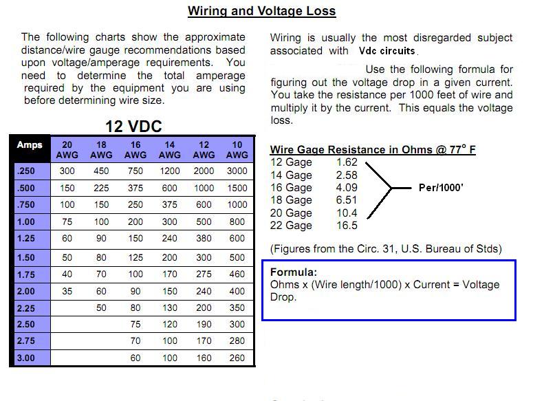
As an example--max current for high beam--10 amps for m-unit. Use calculator at bottom of that link. Even with 10 feet of 12 gauge wire, the voltage drop at full (10 amp) load would be .4 volts. Drop this load to 6 amps, and there is a .2 volt drop.
What I would do is figure out all of your loads. The relatively cheap multimeter I have measures up to 10 amps of current. I would use a battery wired in series with the multimeter (set to amps) and to the individual loads. Make sure it says you can tolerate enough current on your multimeter, otherwise you may damage it. Then you can record exactly what load these will draw-- (coils, dyna, horn, low beam, high beam, etc.) Then stick those load values into the calculator, enter an estimated wire run length (that appears to be single run length for this calculator), and play with the wire size until you get an acceptable voltage drop. You can always default to one size larger than what seems appropriate as a safety factor. Residential maximum voltage drops are typically 3-5%, so I would shoot for a voltage drop of .5 volts or less.
Personally I would run a sizable ground cable from the neg battery terminal to the engine ground, and then at the negative battery terminal run a wire to a bus. How does the OEM ground the frame? I don't remember where this connection is made on the KZ650s and 1000s.
MFolks recommendations seem reasonable--running the values through the calculator will ensure everything is correct. Use higher strand wire if available-it is more flexible and will resist fatigue cracking. As for connections I used to think soldering was king. Unfortunately, solder has the tendency to (capillary) creep up the strands, making the connections stiff and prone to fatigue breaking past the solder. It is going to add cost, but I think I am going to use weatherpack or deutsch crimp on connectors for connections.
What is the cheapest you found the m-unit for?
spieglerusa.com/media/upload/file/munit_manual_en_1_1.pdf
This is the question I was raising---in the owners manual it appeared that on the INPUT side, 12 volts is fed to the switches, and then the switches are connected to the terminals. That way, 12 volts is APPLIED to the input terminals to switch the outputs on. You appear to have it drawn the opposite way---using the switches to GROUND the input terminals to trigger the outputs.
THIS IS WHAT I THOUGHT WHEN I MADE MY PREVIOUS POST---but I realize I was looking at the picture wrong. On the input side, I thought the 12v+ on the input side was the voltage needed for all of the inputs. I now realize that the 12v in is only needed for the ignition lock if used. All other terminals just need to go to ground for output activation.
www.gadgetjq.com/wiring_size_guide.htm
As an example--max current for high beam--10 amps for m-unit. Use calculator at bottom of that link. Even with 10 feet of 12 gauge wire, the voltage drop at full (10 amp) load would be .4 volts. Drop this load to 6 amps, and there is a .2 volt drop.
What I would do is figure out all of your loads. The relatively cheap multimeter I have measures up to 10 amps of current. I would use a battery wired in series with the multimeter (set to amps) and to the individual loads. Make sure it says you can tolerate enough current on your multimeter, otherwise you may damage it. Then you can record exactly what load these will draw-- (coils, dyna, horn, low beam, high beam, etc.) Then stick those load values into the calculator, enter an estimated wire run length (that appears to be single run length for this calculator), and play with the wire size until you get an acceptable voltage drop. You can always default to one size larger than what seems appropriate as a safety factor. Residential maximum voltage drops are typically 3-5%, so I would shoot for a voltage drop of .5 volts or less.
Personally I would run a sizable ground cable from the neg battery terminal to the engine ground, and then at the negative battery terminal run a wire to a bus. How does the OEM ground the frame? I don't remember where this connection is made on the KZ650s and 1000s.
MFolks recommendations seem reasonable--running the values through the calculator will ensure everything is correct. Use higher strand wire if available-it is more flexible and will resist fatigue cracking. As for connections I used to think soldering was king. Unfortunately, solder has the tendency to (capillary) creep up the strands, making the connections stiff and prone to fatigue breaking past the solder. It is going to add cost, but I think I am going to use weatherpack or deutsch crimp on connectors for connections.
What is the cheapest you found the m-unit for?
Please Log in or Create an account to join the conversation.
- royalratch
-
Topic Author
- Offline
- User
-
Registered
- Posts: 144
- Thanks: 10
Re: Custom Loom - WHAT GAUGE CABLES?
14 Dec 2011 05:17 - 14 Dec 2011 09:13
Thanks for replies. I'll be crimping everything with a pro tool and the automotive grade cable, all heatshrunk and wrapped in braided runs where possible.
I really should read the manual! I found this.

I just figured someone may know the specific loads for KZ components. I have an app on my phone that also suggests gauges if you enter loads so could use that.
I'm in the UK - but there's no discounts to be had on M-Units - they go for around £200-220.
I really should read the manual! I found this.
I just figured someone may know the specific loads for KZ components. I have an app on my phone that also suggests gauges if you enter loads so could use that.
I'm in the UK - but there's no discounts to be had on M-Units - they go for around £200-220.
Last edit: 14 Dec 2011 09:13 by royalratch.
Please Log in or Create an account to join the conversation.
- MFolks
-
- Offline
- User
-
Registered
- Posts: 6650
- Thanks: 541
Re: Custom Loom - WHAT GAUGE CABLES?
14 Dec 2011 19:12
To make troubleshooting easier, there are stick on wire numbers available through electrical suppliers, just put one on each end of a wire and make a note of what it is and what circuit function it does. To protect the numbers, cover them with clear heatshrink tubing.
The Mil-Spec wire harnesses(looms) use all white wire, with black ink markings designating circuit functions on white heatshrink tubing.
The Mil-Spec wire harnesses(looms) use all white wire, with black ink markings designating circuit functions on white heatshrink tubing.
1982 GPZ1100 B2
General Dynamics/Convair 1983-1993
GLCM BGM-109 Tomahawk, AGM-129A Advanced Cruise Missile (ACM)
General Dynamics/Convair 1983-1993
GLCM BGM-109 Tomahawk, AGM-129A Advanced Cruise Missile (ACM)
Please Log in or Create an account to join the conversation.
- royalratch
-
Topic Author
- Offline
- User
-
Registered
- Posts: 144
- Thanks: 10
Re: Custom Loom - WHAT GAUGE CABLES?
15 Dec 2011 05:26
Each circuit will have it's own colour wire. The M-Unit has a fault diagnosis LED that tells you what circuit is at fault - then I just investigate the relevant coloured cable.
No more hours of elimination and guesswork!
No more hours of elimination and guesswork!
Please Log in or Create an account to join the conversation.
- Old Man Rock
-
- Offline
- User
-
Registered
- Posts: 6074
- Thanks: 225
Re: Custom Loom - WHAT GAUGE CABLES?
15 Dec 2011 07:44
Maybe this will help....
1976 KZ900-A4
MTC 1075cc.
Camshafts: Kawi GPZ-1100 .375 lift
Head: P&P via Larry Cavanaugh
ZX636 suspension
MIKUNI, RS-34'S...
Kerker 4-1, 1.5" comp baffle.
Dyna-S E.I.
Earls 10 row Oil Cooler
Acewell 2802 Series Speedo/Tach
Innovate LC1 Wideband 02 AFR meter
Phoenix, Az
MTC 1075cc.
Camshafts: Kawi GPZ-1100 .375 lift
Head: P&P via Larry Cavanaugh
ZX636 suspension
MIKUNI, RS-34'S...
Kerker 4-1, 1.5" comp baffle.
Dyna-S E.I.
Earls 10 row Oil Cooler
Acewell 2802 Series Speedo/Tach
Innovate LC1 Wideband 02 AFR meter
Phoenix, Az
Attachments:
Please Log in or Create an account to join the conversation.
Moderators: Street Fighter LTD