
where do you ground? Pictures?
- calvin17d
-
 Topic Author
- Offline
- User
-

Registered
- Posts: 187
- Thanks: 1
Re: where do you ground? Pictures?
12 Feb 2011 17:45
TeK9iNe wrote:
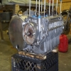
calvin17d wrote:So can we address the items in the picture?
:huh: I thought I did...
The red wire in the middle I assumed was a ground? Any thoughts on why the black/yellow wire is not on the solenoid and is tucked in behind its mounting ear?There are no large red wires on the diagram. I guess I will just toss this then...Large red wires were not used as grounds. Refer to to the wiring diagram I provided. They are VERY HELPFULL.I apologize. I received the bike this way. It seems all the wiring is here but in incorrect areas. Additionally, the large diameter positive (not pictured)lead (not pictured) does not have lugs which will directly fit over the appropriate solenoid terminal(diameter is too small). Me thinks that this short lead (top left) may be serving as a connection to the larger diameter positive lead which has smaller lugs than this short 12 gauge wire on the top left.No problem...Looks to me that your wiring is all @#%$ed (no offence), and that solenoid unit, is not stock. Its a Ford unit scavenged from somewhere. Thats why your leads dont fit, they need to be drilled for that unit.
Can I use all four of these solenoid terminals per the wiring diagram for wiring purposes as if it were stock?
As well, the loose black lead coming from the rectifier is supposed to join in the white terminal to meet its yellow/black lead on the backside of the 6 pin connector. Looks like they wanted to ground that directly to frame. Tying this ground into the 6 pin connector would achieve an engine ground correct?No. It would not make for a very good engine ground. It would just be grounding the battery to frame. The engine ground to - batt terminal should be a large gauge wire. There should also be a ground lead from batt to frame. Again, just check the wiring diagram and you can see all the required conections for ground, rectifier, regulator, everything...
I think what I meant to say was that the black lead from the rectifier had been grounded to the frame near the battery cage. My thought was that the yellow/black wiring provides the entire system with a ground that is properly terminated on the engine block. My suggestion to apply the ground from the rectifier back to the white 6 pin connector at the patch panel was to hopefully get a better ground by jumping onto the yellow/black grounding leads.
Sorry, but to me the whole thing looks F'd, and all wrong. Which is why I say, hook up the solenoid like I said, and use the diagram for the rest.
Best of luck.
")
1976 Kz900 A4
Please Log in or Create an account to join the conversation.
Moderators: Street Fighter LTD