
Joe Hooper (Pit Stop Performance) recommendations for camshaft tuning.
- v.f.
-
 Topic Author
- Offline
- User
-

Registered
- Posts: 74
- Thanks: 26
Joe Hooper (Pit Stop Performance) recommendations for camshaft tuning.
30 Sep 2026 10:52
Joe kindly provided detailed instructions, which I am posting here.
You should aim for a cranking pressure using the starter motor of 160 PSI-180 PSI.It can be adjusted up or down some by adjusting the camshaft center lines.I would recommend you start with 108 degrees. Pit Stop PerformanceCamshaft Degree procedure.Last updated 9-1-2016This procedure will begin with a few bold assumptions. It will assume that the camshafts have been installed using the accepted Kawasaki procedure or Pit Stop Performance procedure for camshaft timing. It is also assumed that the camshaft sprockets which are installed are slotted at the bolt holes to allow camshaft advance and retard movement in relation to the crankshaft. This procedure assumes that the motor has stock camshafts installed. If the camshafts are not stock, the procedure for timing is the same. The procedure for locating top dead center may change, to avoid having valves come into contact with the top dead center finder, leading to valve damage. Finally, it is assumed that the cam chain is sufficiently new that it is actually possible to place the camshafts in the desired position.A few special tools are required for this procedure: Top dead center finder Dial gauge with magnetic base Degree wheel PointerThe dial gauge with magnetic base, the top dead center finder and the degree wheel are all available from Pit Stop Performance either individually or in a complete kit. The pointer can be fabricated out of a length of wire coat hanger. Bend as required with a pair of pliers or two so that the pointer can be secured to a dyno cover case hole with a 6mm screw along with a large diameter washer and the free end can point to the edge of the degree wheel when it is mounted on the end of the crankshaft. The pointer end may be sharpened on a bench grinder. The top dead center finder can also be fabricated if you do not wish to purchase one. Bust up an old spark plug to make it. The porcelain can be removed by placing it in a vice and tightening until the porcelain breaks (be sure to wear safety glasses). The remainder of the insides can be removed with a drift pin and a hammer. Cut off the negative electrode with a pair of diagonal cutters. Next, drill with a 5/16” drill and tap the inside of the plug with a 3/8” X 16 TPI tap. Obtain a 3/8” X 16 TPI bolt, 3 ½” long and insert from the top. You now have a top dead center finder that can be added to your tool box.One rule that should always be followed when timing camshafts is that the motor should only be rotated in the same direction as it operates. This rule should be followed unless the procedure absolutely requires you to rotate the motor in the opposite direction. So, for our purposes, we are only going to rotate the motor from the ignition side using a 17mm wrench. We are only going to rotate it in the clockwise direction (from the ignition side) unless instructed to do otherwise in this procedure.
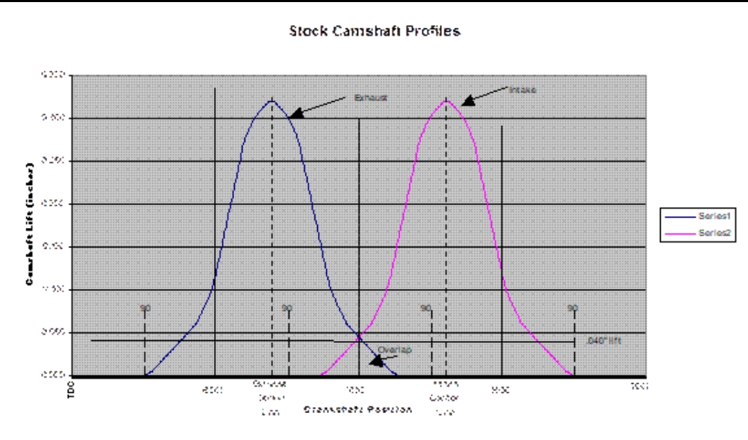
First, mount the degree wheel on the dyno side of the motor. Rotate the crankshaft from the ignition side to the 1-4 T mark on the ignition advancer. Rotate the degree wheel as required and set your pointer on TDC. Note that this is a roughing in procedure. A more accurate TDC will be determined shortly. Rotate the crankshaft counter clockwise from the ignition side until the degree wheel is approximately 20 degrees Before TDC (BTDC). This is a good time to familiarize yourself with the difference between before top dead center (BTDC) and after top dead center (ATDC). If you are looking at the degree wheel on the dyno or left side of the motor, the rotation of the motor while running is counter clockwise. So, if the pointer is at 20 and you would have to rotate the motor counter clockwise from the dyno side to reach TDC, then the motor is at 20 degrees before TDC, or 20 degrees BTDC. Top Dead Center location procedureNext, install your newly built top dead center finder in the number four cylinder. Remove the bolt before installation. Install the bolt and rotate by hand until it contacts the top of the piston. Rotate the crankshaft clockwise from the ignition side and hold the piston against the bolt of the top dead center finder. Have someone else read the degree wheel for you while you are maintaining tension against the bolt of the top dead center finder. It should be reading something close to 20 BTDC, maybe a little less. Right this number down. Now, rotate the motor counter clockwise from the ignition side until the piston again stops against the top dead center finder bolt. Have your friend read the degree wheel again while you are maintaining tension against the bolt of the top dead center finder. It should be reading some number close to 20 ATDC. Write this number down. Add the two numbers together and divide by two. The result is where you want to relocate your pointer. Move the pointer only while you are maintaining tension against the bolt of the top dead center finder. Repeat the Top Dead Center location procedure. The crankshaft should stop at the same number before and after TDC. Once complete, back the motor off so that the piston is not in contact with the top dead center finder bolt, and remove the bolt and the top dead center finder from the spark plug hole. You are now ready to determine the timing of your camshafts. The method to be used is the Pit Stop Performance center line method. We will be calculating the center line of one lobe of each camshaft. The center line is the middle of the highest point on the lobe, but it can not be measured directly. We will calculate the position of the center line by picking a point on the opening ramp and the same point on the closing ramp. We will then calculate the point in between (center line).The camshaft timing preferred by Pit Stop Performance is known as “split overlap”. The overlap is the period of time when both the intake and the exhaust valves are open. By splitting the overlap, we will be dividing the overlap so that half of it occurs before TDC and half of it occurs after TDC. When you split the overlap, it means that the center line of each camshaft will be the same number. The exhaust center line will be BTDC and the intake center line will be ATDC. Stock camshafts set to factory Kawasaki specifications have centerlines of 110 degrees.Take a look at the Stock Camshaft Profiles graph below. Note that there are three points on the graph that are marked TDC. The one furthest to the left and the one furthest to the right are actually the same point. The graph keeps repeating as the motor runs. From one TDC to the next represents one complete revolution of the motor. It takes two complete revolutions of the motor to make one complete cycle. Note the portion of the graph identified as overlap. This is where both valves are open at the same time. The horizontal lines on the graph represent valve lift in inches. The vertical lines on the graph represent important points as the motor rotates. The bell shaped curves represent the intake and exhaust valve openings in relation to crankshaft position. In this graph both camshafts are shown at the factory settings of 110 degrees center line. The graph comes to a point at the top, it shouldn’t. I could not make the graph look right when I pasted it in from Excel.
applications, the center lines may go as high as 116 degrees. A good rule of thumb is that a lower center line will yield more torque and lower end throttle response and a higher center line will yield more maximum power output a higher RPM.Once both camshafts are correctly timed and all six bolts are tight, the last step is to remove the camshaft bolts one at a time and apply a drop of Loctite thread locker. Reinstall the bolts and tighten to 120 inch pounds.*******Do not forget this last step.*******The torque of the camshafts bolts (three per camshaft) should be checked by a second person, completely independent of the person who originally performed the torqueing. Joe HooperPit Stop Performance
You should aim for a cranking pressure using the starter motor of 160 PSI-180 PSI.It can be adjusted up or down some by adjusting the camshaft center lines.I would recommend you start with 108 degrees. Pit Stop PerformanceCamshaft Degree procedure.Last updated 9-1-2016This procedure will begin with a few bold assumptions. It will assume that the camshafts have been installed using the accepted Kawasaki procedure or Pit Stop Performance procedure for camshaft timing. It is also assumed that the camshaft sprockets which are installed are slotted at the bolt holes to allow camshaft advance and retard movement in relation to the crankshaft. This procedure assumes that the motor has stock camshafts installed. If the camshafts are not stock, the procedure for timing is the same. The procedure for locating top dead center may change, to avoid having valves come into contact with the top dead center finder, leading to valve damage. Finally, it is assumed that the cam chain is sufficiently new that it is actually possible to place the camshafts in the desired position.A few special tools are required for this procedure: Top dead center finder Dial gauge with magnetic base Degree wheel PointerThe dial gauge with magnetic base, the top dead center finder and the degree wheel are all available from Pit Stop Performance either individually or in a complete kit. The pointer can be fabricated out of a length of wire coat hanger. Bend as required with a pair of pliers or two so that the pointer can be secured to a dyno cover case hole with a 6mm screw along with a large diameter washer and the free end can point to the edge of the degree wheel when it is mounted on the end of the crankshaft. The pointer end may be sharpened on a bench grinder. The top dead center finder can also be fabricated if you do not wish to purchase one. Bust up an old spark plug to make it. The porcelain can be removed by placing it in a vice and tightening until the porcelain breaks (be sure to wear safety glasses). The remainder of the insides can be removed with a drift pin and a hammer. Cut off the negative electrode with a pair of diagonal cutters. Next, drill with a 5/16” drill and tap the inside of the plug with a 3/8” X 16 TPI tap. Obtain a 3/8” X 16 TPI bolt, 3 ½” long and insert from the top. You now have a top dead center finder that can be added to your tool box.One rule that should always be followed when timing camshafts is that the motor should only be rotated in the same direction as it operates. This rule should be followed unless the procedure absolutely requires you to rotate the motor in the opposite direction. So, for our purposes, we are only going to rotate the motor from the ignition side using a 17mm wrench. We are only going to rotate it in the clockwise direction (from the ignition side) unless instructed to do otherwise in this procedure.
First, mount the degree wheel on the dyno side of the motor. Rotate the crankshaft from the ignition side to the 1-4 T mark on the ignition advancer. Rotate the degree wheel as required and set your pointer on TDC. Note that this is a roughing in procedure. A more accurate TDC will be determined shortly. Rotate the crankshaft counter clockwise from the ignition side until the degree wheel is approximately 20 degrees Before TDC (BTDC). This is a good time to familiarize yourself with the difference between before top dead center (BTDC) and after top dead center (ATDC). If you are looking at the degree wheel on the dyno or left side of the motor, the rotation of the motor while running is counter clockwise. So, if the pointer is at 20 and you would have to rotate the motor counter clockwise from the dyno side to reach TDC, then the motor is at 20 degrees before TDC, or 20 degrees BTDC. Top Dead Center location procedureNext, install your newly built top dead center finder in the number four cylinder. Remove the bolt before installation. Install the bolt and rotate by hand until it contacts the top of the piston. Rotate the crankshaft clockwise from the ignition side and hold the piston against the bolt of the top dead center finder. Have someone else read the degree wheel for you while you are maintaining tension against the bolt of the top dead center finder. It should be reading something close to 20 BTDC, maybe a little less. Right this number down. Now, rotate the motor counter clockwise from the ignition side until the piston again stops against the top dead center finder bolt. Have your friend read the degree wheel again while you are maintaining tension against the bolt of the top dead center finder. It should be reading some number close to 20 ATDC. Write this number down. Add the two numbers together and divide by two. The result is where you want to relocate your pointer. Move the pointer only while you are maintaining tension against the bolt of the top dead center finder. Repeat the Top Dead Center location procedure. The crankshaft should stop at the same number before and after TDC. Once complete, back the motor off so that the piston is not in contact with the top dead center finder bolt, and remove the bolt and the top dead center finder from the spark plug hole. You are now ready to determine the timing of your camshafts. The method to be used is the Pit Stop Performance center line method. We will be calculating the center line of one lobe of each camshaft. The center line is the middle of the highest point on the lobe, but it can not be measured directly. We will calculate the position of the center line by picking a point on the opening ramp and the same point on the closing ramp. We will then calculate the point in between (center line).The camshaft timing preferred by Pit Stop Performance is known as “split overlap”. The overlap is the period of time when both the intake and the exhaust valves are open. By splitting the overlap, we will be dividing the overlap so that half of it occurs before TDC and half of it occurs after TDC. When you split the overlap, it means that the center line of each camshaft will be the same number. The exhaust center line will be BTDC and the intake center line will be ATDC. Stock camshafts set to factory Kawasaki specifications have centerlines of 110 degrees.Take a look at the Stock Camshaft Profiles graph below. Note that there are three points on the graph that are marked TDC. The one furthest to the left and the one furthest to the right are actually the same point. The graph keeps repeating as the motor runs. From one TDC to the next represents one complete revolution of the motor. It takes two complete revolutions of the motor to make one complete cycle. Note the portion of the graph identified as overlap. This is where both valves are open at the same time. The horizontal lines on the graph represent valve lift in inches. The vertical lines on the graph represent important points as the motor rotates. The bell shaped curves represent the intake and exhaust valve openings in relation to crankshaft position. In this graph both camshafts are shown at the factory settings of 110 degrees center line. The graph comes to a point at the top, it shouldn’t. I could not make the graph look right when I pasted it in from Excel.
applications, the center lines may go as high as 116 degrees. A good rule of thumb is that a lower center line will yield more torque and lower end throttle response and a higher center line will yield more maximum power output a higher RPM.Once both camshafts are correctly timed and all six bolts are tight, the last step is to remove the camshaft bolts one at a time and apply a drop of Loctite thread locker. Reinstall the bolts and tighten to 120 inch pounds.*******Do not forget this last step.*******The torque of the camshafts bolts (three per camshaft) should be checked by a second person, completely independent of the person who originally performed the torqueing. Joe HooperPit Stop Performance
Please Log in or Create an account to join the conversation.
- Injected
-
- Offline
- User
-
Registered
- Posts: 1829
- Thanks: 1278
Re: Joe Hooper (Pit Stop Performance) recommendations for camshaft tuning.
01 Oct 2026 07:31
Did you adjust your cam timing to try and reduce the cranking compression on your 1400 engine? You mentioned engine ping in another thread.
I realize you can only adjust so far with the cams before have to look at other methods.
I realize you can only adjust so far with the cams before have to look at other methods.
1978 KZ650B2 w 1197cc Z1 engine
1977 KZ650B1 w 750cc Spectre engine
1979 KZ650C3 w 831cc Hot Rod engine
1978 KZ650C2 w 762cc DFI project
1977 KZ650C1 stock restoration project
1978 KZ650B2 modified project
1977 KZ650B1 w 750cc Spectre engine
1979 KZ650C3 w 831cc Hot Rod engine
1978 KZ650C2 w 762cc DFI project
1977 KZ650C1 stock restoration project
1978 KZ650B2 modified project
Please Log in or Create an account to join the conversation.
- v.f.
-
Topic Author
- Offline
- User
-
Registered
- Posts: 74
- Thanks: 26
Re: Joe Hooper (Pit Stop Performance) recommendations for camshaft tuning.
01 Oct 2026 07:42
Hi! Yes, I tried shifting the valve timing, but I didn't get the expected result and didn't like how the engine ran; I also tried retarding the ignition timing. But again, the result didn't satisfy me. I tried running a richer mixture—that didn't help at all. Now I've taken the engine apart again and am going to lower the geometric compression ratio. )))
Please Log in or Create an account to join the conversation.
- v.f.
-
Topic Author
- Offline
- User
-
Registered
- Posts: 74
- Thanks: 26
Re: Joe Hooper (Pit Stop Performance) recommendations for camshaft tuning.
01 Oct 2026 11:50
Actually, I’m considering using the ignition system from a Suzuki GSX 1100F. It has slightly less advance at maximum RPM—roughly 35–38 degrees, compared to the GPZ 1100’s 40 degrees. I wonder if anyone on the forum has tried this setup? Especially since the Suzuki’s ignition pickup is mounted on a plate, making it possible to make it adjustable, whereas the GPZ 1100 sensors offer no such adjustability.
Please Log in or Create an account to join the conversation.
- Wookie58
-

- Offline
- Moderator
-

Registered
- Posts: 6878
- Thanks: 4330
Re: Joe Hooper (Pit Stop Performance) recommendations for camshaft tuning.
01 Oct 2026 12:51I don't know what facilities you have but I have been playing with the timing on the GPZ set-up I'm using on my "J" build. I had removed 2mm from the trailing edge of the trigger to bring the timing into line with "true TDC" (factory TDC mark is retarded 3 degrees) I have returned it to stock in an attempt to rectify initial start issues but I don't think it was related. If you want to retard the ignition lay a bead of weld along the trailing edge of the trigger and grind to size (the pulse occurs as the trigger rotor leaves the magnetic field)Actually, I’m considering using the ignition system from a Suzuki GSX 1100F. It has slightly less advance at maximum RPM—roughly 35–38 degrees, compared to the GPZ 1100’s 40 degrees. I wonder if anyone on the forum has tried this setup? Especially since the Suzuki’s ignition pickup is mounted on a plate, making it possible to make it adjustable, whereas the GPZ 1100 sensors offer no such adjustability.
1982 KZ1000 Ltd
www.kzrider.com/forum/11-projects/617631...-82-begins?start=192
kzrider.com/forum/faq-wiki/616810-electr...-fault-finding-guide
www.kzrider.com/forum/11-projects/617631...-82-begins?start=192
kzrider.com/forum/faq-wiki/616810-electr...-fault-finding-guide
The following user(s) said Thank You: v.f.
Please Log in or Create an account to join the conversation.
- zed1015
-

- Offline
- User
-
Registered
- Posts: 3362
- Thanks: 2071
Re: Joe Hooper (Pit Stop Performance) recommendations for camshaft tuning.
01 Oct 2026 14:49 - 01 Oct 2026 15:35
You can always slot the three mounting holes to get some adjustment instead of modifying the rotor but either way you would retard the static timing by the same amount as full advance but a couple of degrees should be ok although not enough if the detonation is prominent.
Apart from dropping the comp which you likely have to do dual plugging also helps combat detonation and allows another 5 degrees or so of retard.
Apart from dropping the comp which you likely have to do dual plugging also helps combat detonation and allows another 5 degrees or so of retard.
AIR CORRECTOR JETS FOR VM CARBS AND ETHANOL RESISTANT VITON CHOKE PLUNGER SEAL REPLACMENT FOR ALL CLASSIC AND MODERN MOTORCYCLE CARBURETTORS
www.kzrider.com/forum/23-for-sale/611992...lide-mikunis?start=1
www.kzrider.com/forum/23-for-sale/611992...lide-mikunis?start=1
Last edit: 01 Oct 2026 15:35 by zed1015.
The following user(s) said Thank You: v.f.
Please Log in or Create an account to join the conversation.
- Wookie58
-
- Offline
- Moderator
-
Registered
- Posts: 6878
- Thanks: 4330
Re: Joe Hooper (Pit Stop Performance) recommendations for camshaft tuning.
01 Oct 2026 15:42
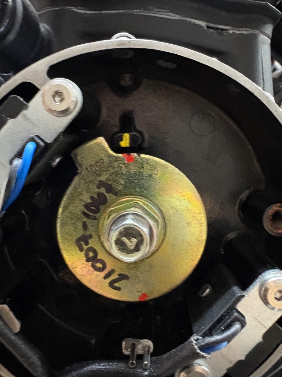
Rob the GPZ set up doesn’t have the three screws, the pick up’s are fixed
1982 KZ1000 Ltd
www.kzrider.com/forum/11-projects/617631...-82-begins?start=192
kzrider.com/forum/faq-wiki/616810-electr...-fault-finding-guide
www.kzrider.com/forum/11-projects/617631...-82-begins?start=192
kzrider.com/forum/faq-wiki/616810-electr...-fault-finding-guide
The following user(s) said Thank You: v.f.
Please Log in or Create an account to join the conversation.
- zed1015
-
- Offline
- User
-
Registered
- Posts: 3362
- Thanks: 2071
Re: Joe Hooper (Pit Stop Performance) recommendations for camshaft tuning.
01 Oct 2026 16:09 - 01 Oct 2026 16:10
All depends which GPZ1100 it is.
Only the Unitracks are fixed in the housing, the earlier B's are on a backplate like the MK2's .
The bike in VF's previous posts is a 1000R though which should have the earlier backplate type unless it's a mongrel.
Easy enough to swap housings and mix and match parts to get something that's adjustable but then it'd probably be more straight forward just fitting a Dyna 2000 to maintain the correct static and only retard full advance..
AIR CORRECTOR JETS FOR VM CARBS AND ETHANOL RESISTANT VITON CHOKE PLUNGER SEAL REPLACMENT FOR ALL CLASSIC AND MODERN MOTORCYCLE CARBURETTORS
www.kzrider.com/forum/23-for-sale/611992...lide-mikunis?start=1
www.kzrider.com/forum/23-for-sale/611992...lide-mikunis?start=1
Last edit: 01 Oct 2026 16:10 by zed1015.
The following user(s) said Thank You: v.f., Wookie58
Please Log in or Create an account to join the conversation.
- Injected
-
- Offline
- User
-
Registered
- Posts: 1829
- Thanks: 1278
Re: Joe Hooper (Pit Stop Performance) recommendations for camshaft tuning.
01 Oct 2026 21:21 - 01 Oct 2026 21:21
Since you are using such a large piston it would be advantageous for you to run a dual plug setup and retard the ignition.
The extra spark over the other side of such a large dome will spread out the flame pattern and possibly help with the detonation issue. You can dial the timing down from 38 to 32 or 34 degrees.
There is lots of room under the big bike tanks to run two sets of 1.5 ohm coils.
The extra spark over the other side of such a large dome will spread out the flame pattern and possibly help with the detonation issue. You can dial the timing down from 38 to 32 or 34 degrees.
There is lots of room under the big bike tanks to run two sets of 1.5 ohm coils.
1978 KZ650B2 w 1197cc Z1 engine
1977 KZ650B1 w 750cc Spectre engine
1979 KZ650C3 w 831cc Hot Rod engine
1978 KZ650C2 w 762cc DFI project
1977 KZ650C1 stock restoration project
1978 KZ650B2 modified project
1977 KZ650B1 w 750cc Spectre engine
1979 KZ650C3 w 831cc Hot Rod engine
1978 KZ650C2 w 762cc DFI project
1977 KZ650C1 stock restoration project
1978 KZ650B2 modified project
Last edit: 01 Oct 2026 21:21 by Injected. Reason: sp
The following user(s) said Thank You: v.f.
Please Log in or Create an account to join the conversation.
- v.f.
-
Topic Author
- Offline
- User
-
Registered
- Posts: 74
- Thanks: 26
Re: Joe Hooper (Pit Stop Performance) recommendations for camshaft tuning.
02 Oct 2026 12:46
I’m currently running a Dyna S, but I don’t like how the centrifugal advance mechanism performs. It hits its maximum advance of around 40° by the time the engine reaches ~3,000 RPM. I tried bending the stop tabs, but that’s hardly the "samurai way" of doing things. It seems to me that the advance curve is essentially too abrupt—it jumps up suddenly—which generally isn't great for any engine. But that’s just my opinion.
Please Log in or Create an account to join the conversation.
- v.f.
-
Topic Author
- Offline
- User
-
Registered
- Posts: 74
- Thanks: 26
Re: Joe Hooper (Pit Stop Performance) recommendations for camshaft tuning.
02 Oct 2026 12:53
Detonation occurs at mid-range RPM when the throttle is opened abruptly. Above 7,000–7,500 RPM, it disappears—or at least I can't hear or feel it. Judging by the spark plugs, the mixture is spot-on, although the old plugs look like they were running very rich following my recent mixture experiments. I suspect a smoother ignition curve might improve things, but then again, that’s something that has to be determined through trial and error.
Please Log in or Create an account to join the conversation.
- v.f.
-
Topic Author
- Offline
- User
-
Registered
- Posts: 74
- Thanks: 26
Re: Joe Hooper (Pit Stop Performance) recommendations for camshaft tuning.
02 Oct 2026 13:02
Yes, it’s a J-model, but I installed a Dyna S and an MSD MC-3 a long time ago—hoping that the spark energy would be sufficient even with just a single spark plug. Apparently, it wasn't enough. As far as I know, the ignition system from the '83–'85 GPZ 1100 is hit-or-miss; it depends on the link between the ignition module and the fuel injection control unit. Unfortunately, I don't know the part numbers for the units that work without the injection system. Besides, the ignition curve on the '83–'84 GPZ is the same as on the J-model, so it would likely work well on a stock bike.
Please Log in or Create an account to join the conversation.
Moderators: Street Fighter LTD