- Posts: 63
- Thank you received: 0
KZR's Bikes of the Month for 2024
-
Slmjim and BEBE's Z1 BOTM October '24euror
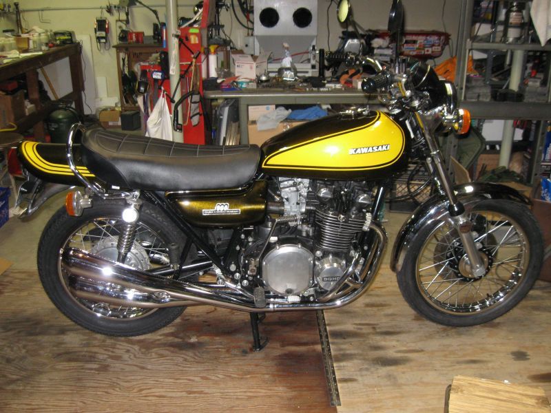 Slmjim and BEBE's Z1 BOTM October '24
 -
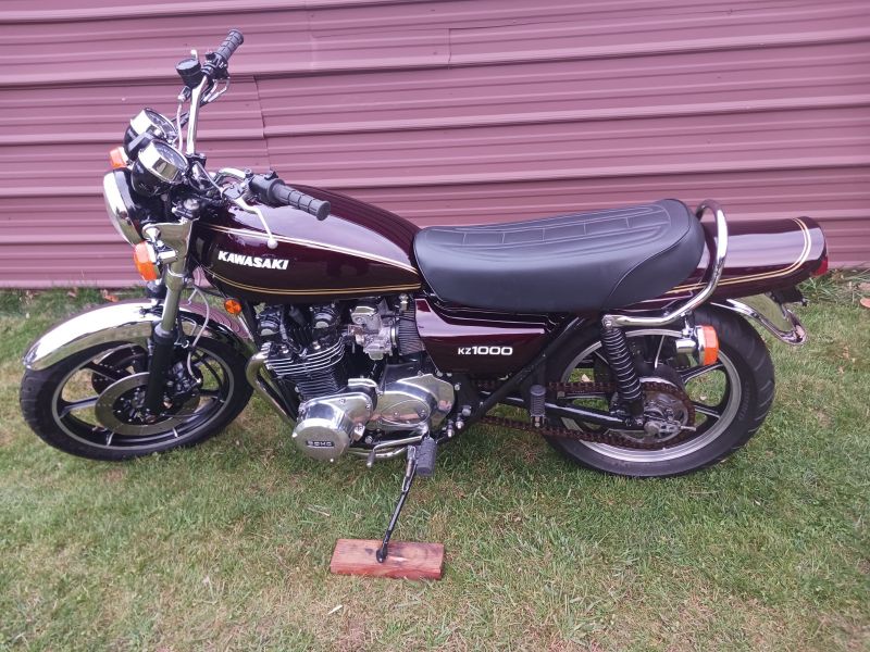
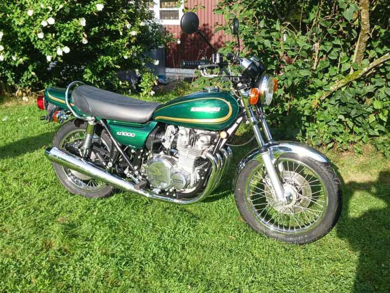
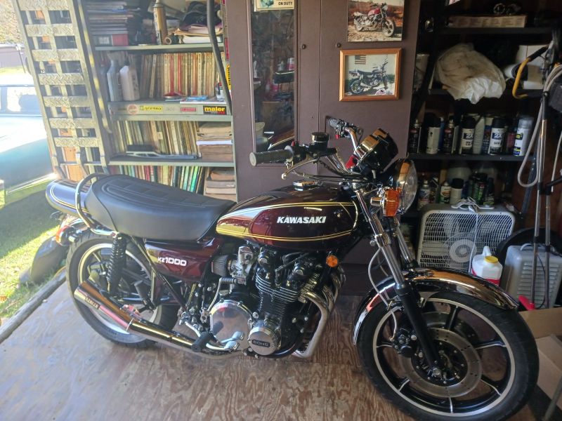
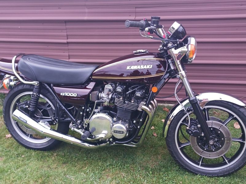
March '24 BOTM '77KZ1000 by Kelly Ekzr botm march02
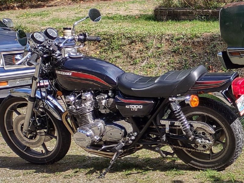 March '24 BOTM '77KZ1000 by Kelly E
 -
Ronnie V's BOTM for December 2024ronnievs botm december 2024Ronnie V's BOTM for December 2024
-
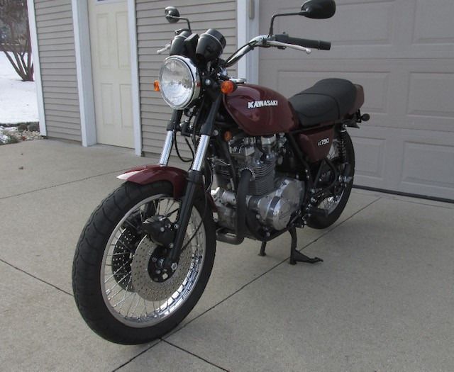
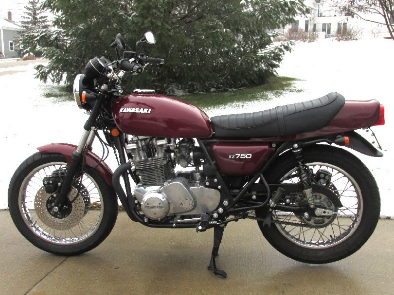
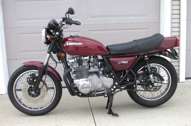
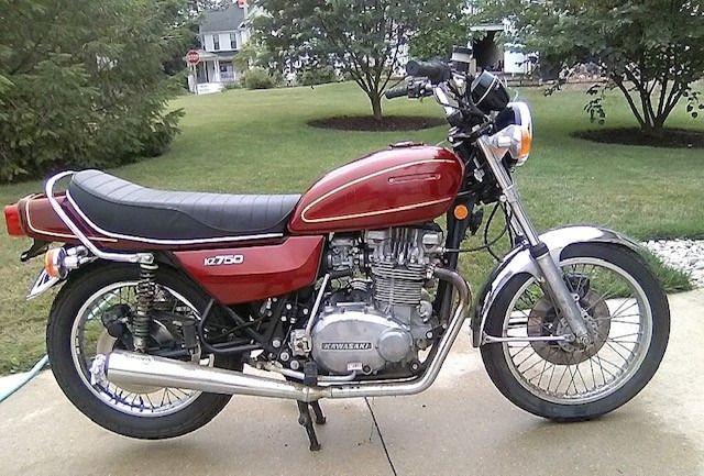
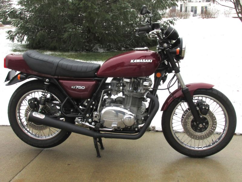
Feb '24 BOTM KZ750 by RustyB1kzr botm feburary05Feb '24 BOTM KZ750 by RustyB1
-
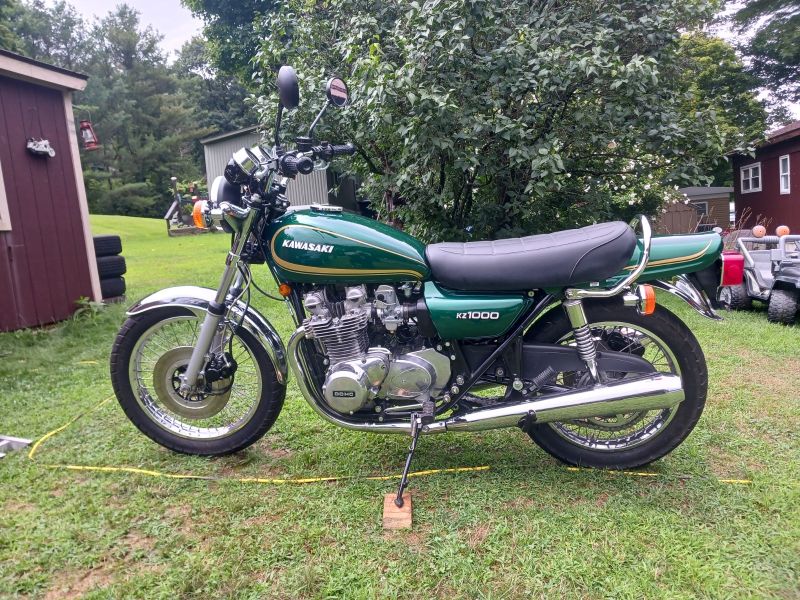
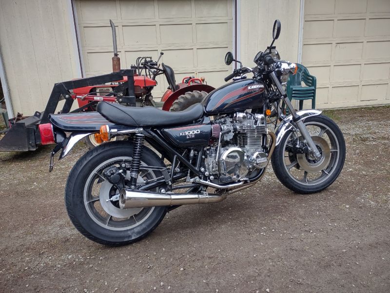
BOTM for January 2024 RonnieV's KZ1000kzr botm jauuary02BOTM for January 2024 RonnieV's KZ1000
-
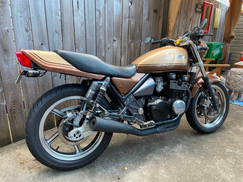
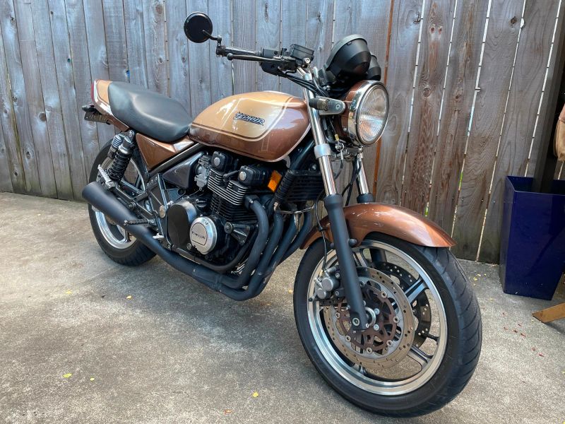
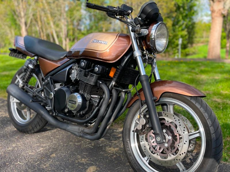
Stereordinary's 550 Zephyr BOTM September '24kzr botm september01Stereordinary's 550 Zephyr BOTM September '24
-
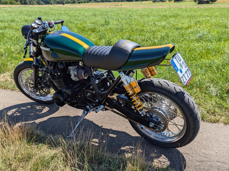
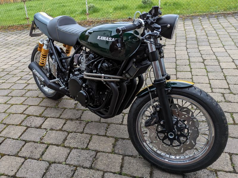
Calum's RestoModded KZ1000 BOTM November '24picCalum's RestoModded KZ1000 BOTM November '24
-
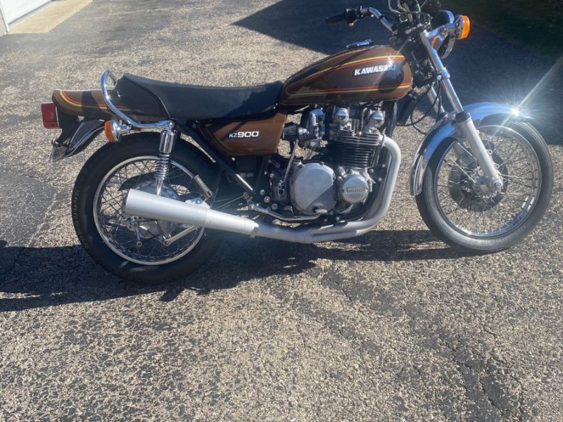
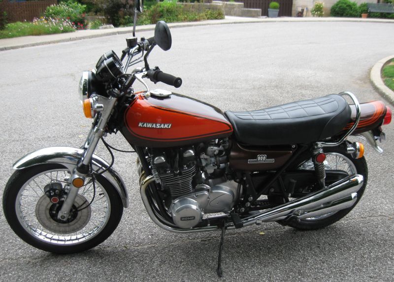
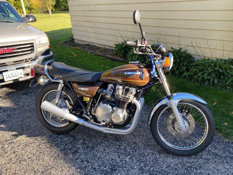
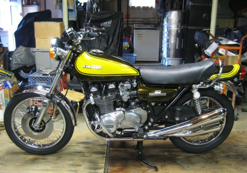
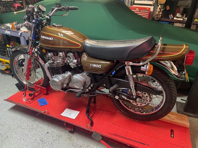
WheelHop's KZ900 BOTM for April '24kzr botm april02WheelHop's KZ900 BOTM for April '24
-
Calum's RestoModded KZ1000 BOTM November '24picCalum's RestoModded KZ1000 BOTM November '24
-
Stereordinary's 550 Zephyr BOTM September '24kzr botm september03Stereordinary's 550 Zephyr BOTM September '24
-
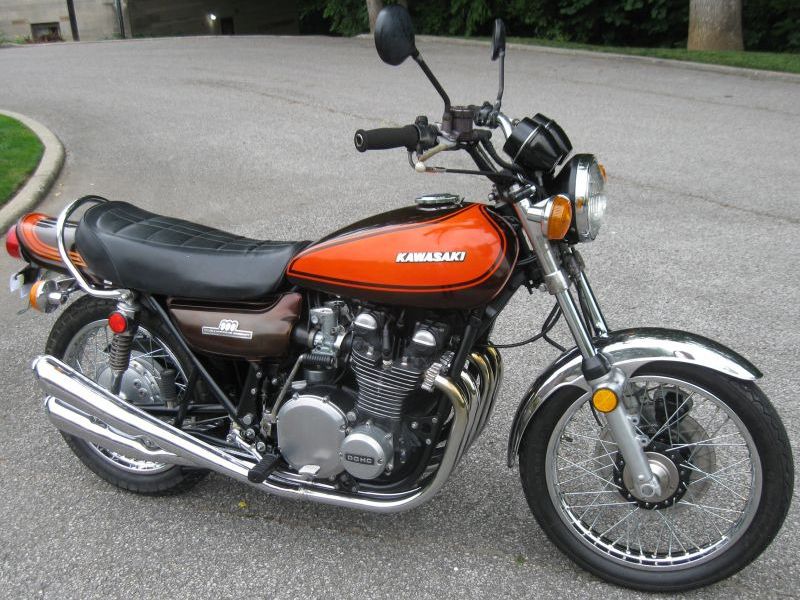
Slmjim+BEBE's '73 Z1 BOTM May '24kzr botm may01Slmjim+BEBE's '73 Z1 BOTM May '24
-
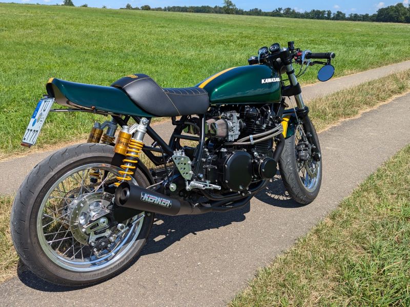
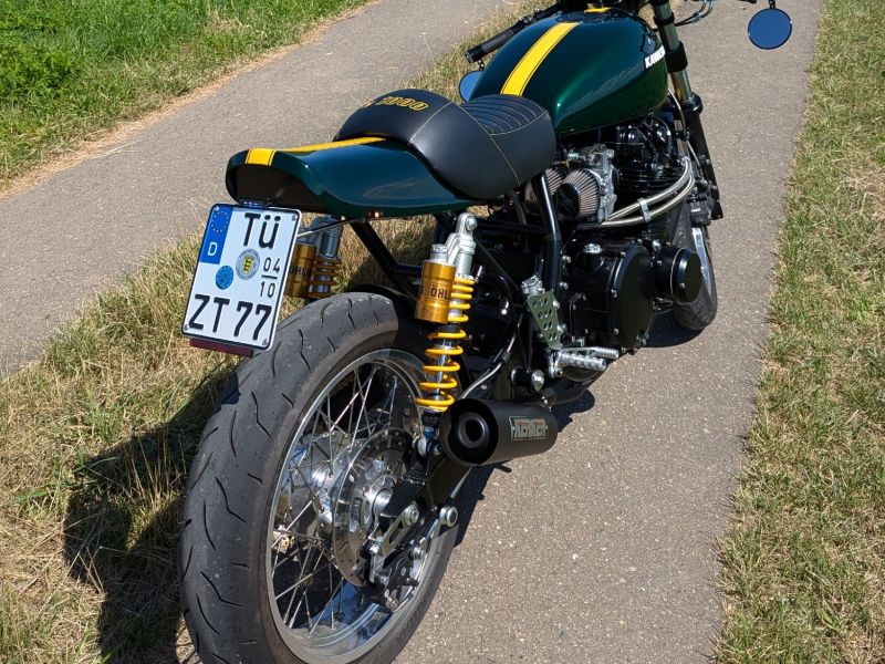
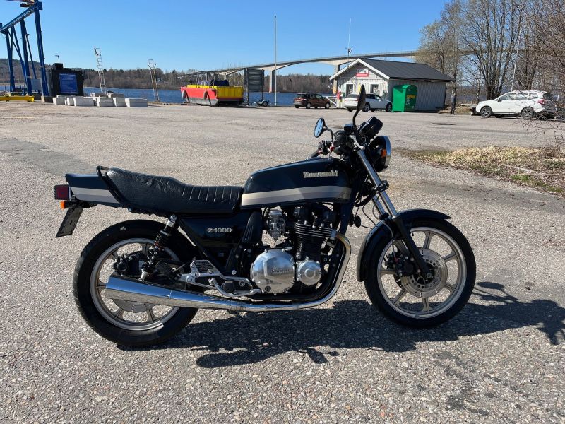
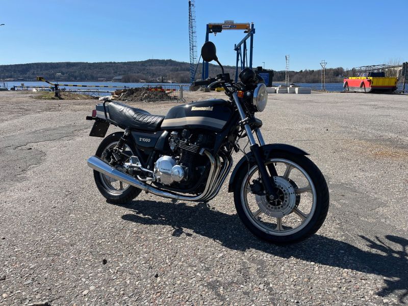
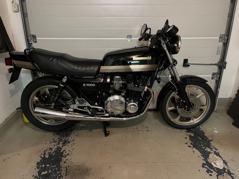
Jonas' Z1000 BOTM July '24kzr botm july03Jonas' Z1000 BOTM July '24
-
Jonas' Z1000 BOTM July '24kzr botm july04Jonas' Z1000 BOTM July '24
-
Feb '24 BOTM KZ750 by RustyB1kzr botm feburary04Feb '24 BOTM KZ750 by RustyB1
-
Ronnie V's BOTM for December 2024ronnievs botm december 2024Ronnie V's BOTM for December 2024
-
March '24 BOTM '77KZ1000 by Kelly Ekzr botm march01March '24 BOTM '77KZ1000 by Kelly E
-
Slmjim+BEBE's '73 Z1 BOTM May '24kzr botm may02Slmjim+BEBE's '73 Z1 BOTM May '24
-
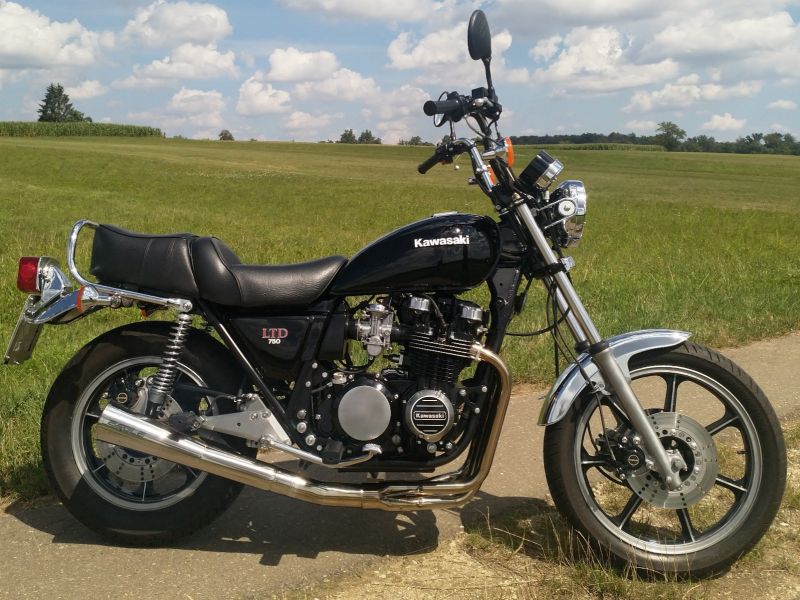
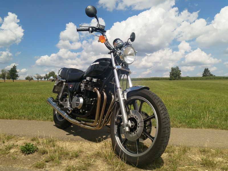
Calum's 1980 KZ750 LTD BOTM June '24kzr botm june01Calum's 1980 KZ750 LTD BOTM June '24
-
Feb '24 BOTM KZ750 by RustyB1kzr botm feburary02Feb '24 BOTM KZ750 by RustyB1
-
Calum's 1980 KZ750 LTD BOTM June '24kzr botm june02Calum's 1980 KZ750 LTD BOTM June '24
-
WheelHop's KZ900 BOTM for April '24kzr botm april03WheelHop's KZ900 BOTM for April '24
-
Jonas' Z1000 BOTM July '24kzr botm july02Jonas' Z1000 BOTM July '24
-
Slmjim and BEBE's Z1 BOTM October '24euroz lSlmjim and BEBE's Z1 BOTM October '24
-
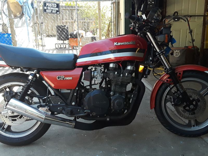
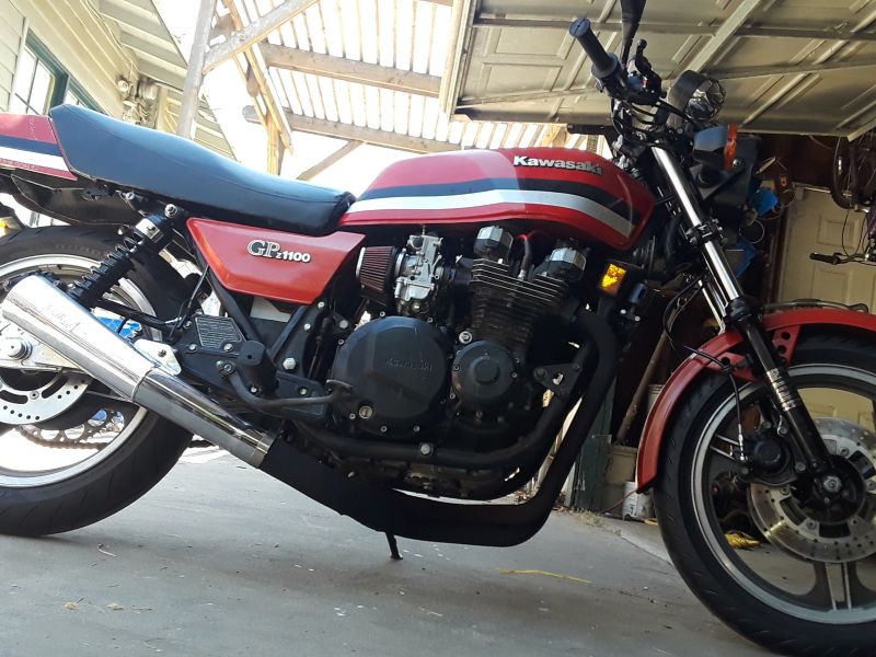
Slayer61's GPZ1100 BOTM August '24kzr botm august01Slayer61's GPZ1100 BOTM August '24
-
Jonas' Z1000 BOTM July '24kzr botm july01Jonas' Z1000 BOTM July '24
-
Calum's RestoModded KZ1000 BOTM November '24picCalum's RestoModded KZ1000 BOTM November '24
-
BOTM for January 2024 RonnieV's KZ1000kzr botm january01BOTM for January 2024 RonnieV's KZ1000
-
Slayer61's GPZ1100 BOTM August '24kzr botm august02Slayer61's GPZ1100 BOTM August '24
-
Calum's RestoModded KZ1000 BOTM November '24picCalum's RestoModded KZ1000 BOTM November '24
-
Feb '24 BOTM KZ750 by RustyB1kzr botm feburary01Feb '24 BOTM KZ750 by RustyB1
-
Slayer61's GPZ1100 BOTM August '24kzr botm august03Slayer61's GPZ1100 BOTM August '24
-
WheelHop's KZ900 BOTM for April '24kzr botm april01WheelHop's KZ900 BOTM for April '24
-
BOTM for January 2024 RonnieV's KZ1000kzr botm january03BOTM for January 2024 RonnieV's KZ1000
-
Feb '24 BOTM KZ750 by RustyB1kzr botm feburary03Feb '24 BOTM KZ750 by RustyB1
-
Stereordinary's 550 Zephyr BOTM September '24kzr botm september02Stereordinary's 550 Zephyr BOTM September '24

