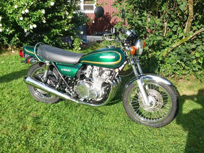
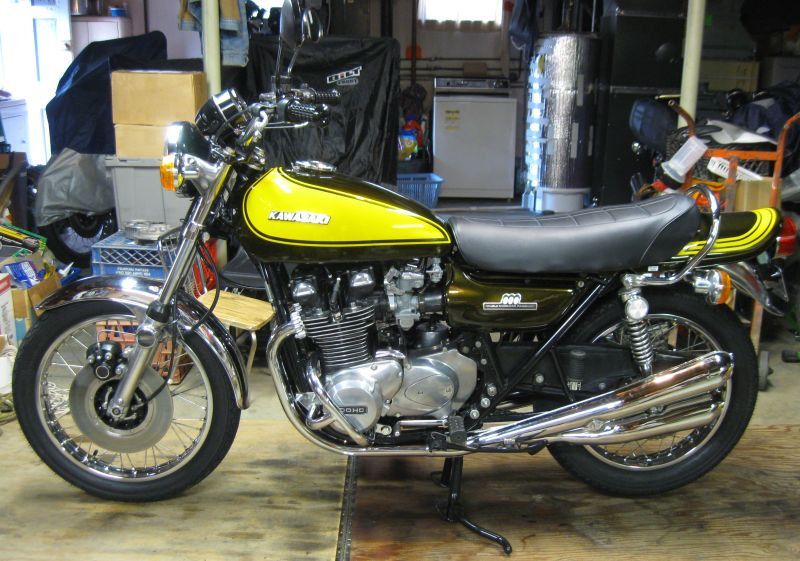
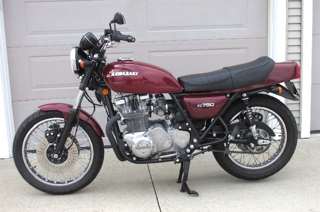
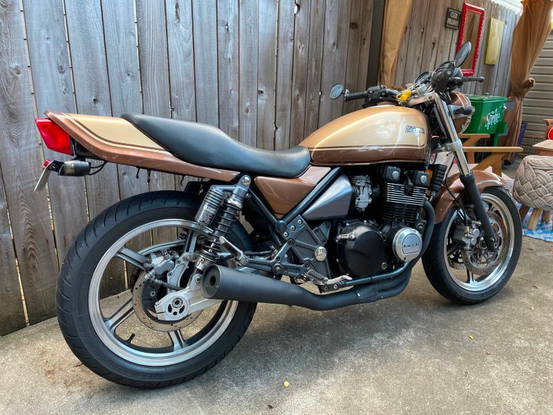
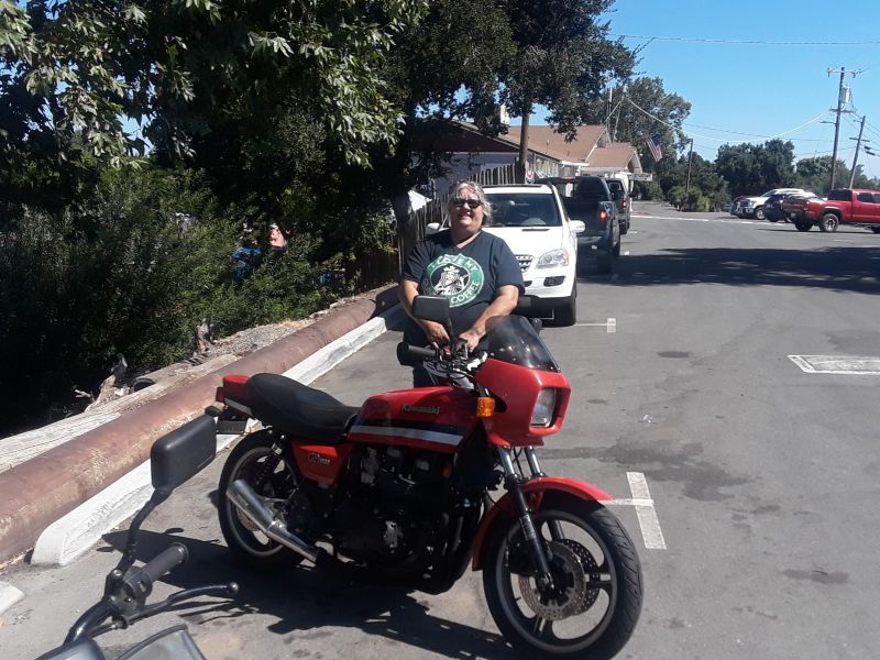
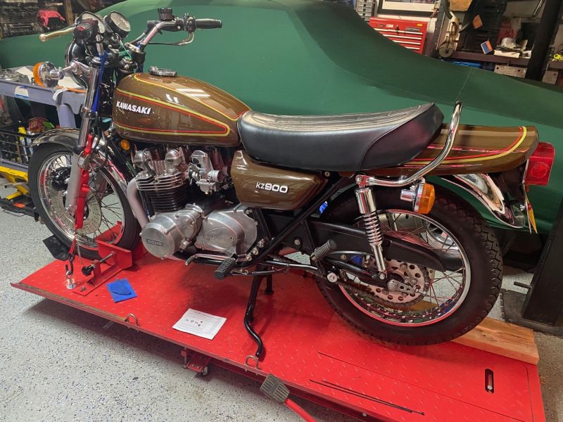
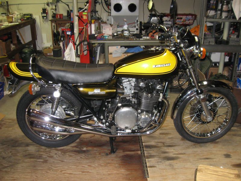
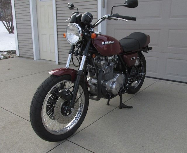
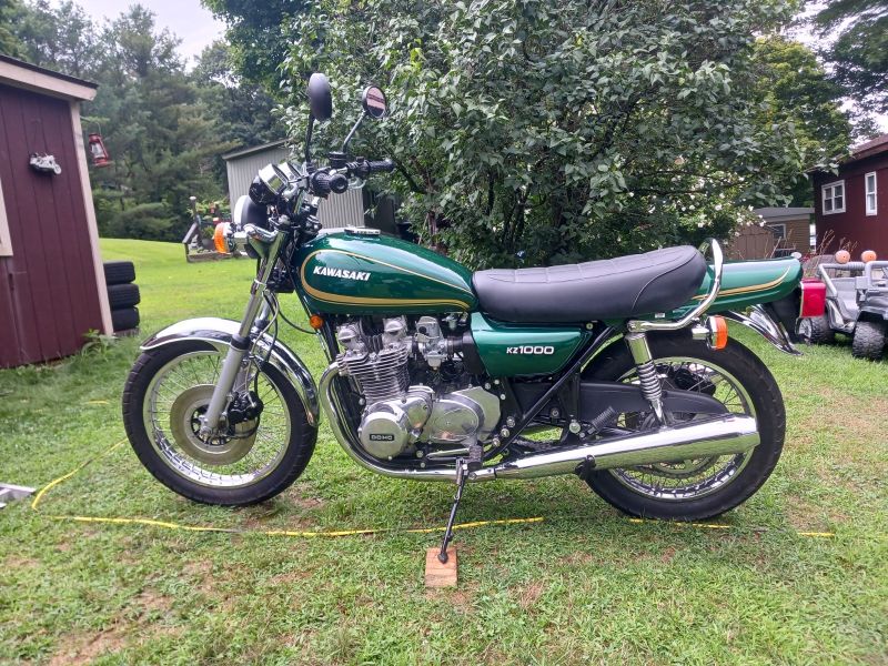
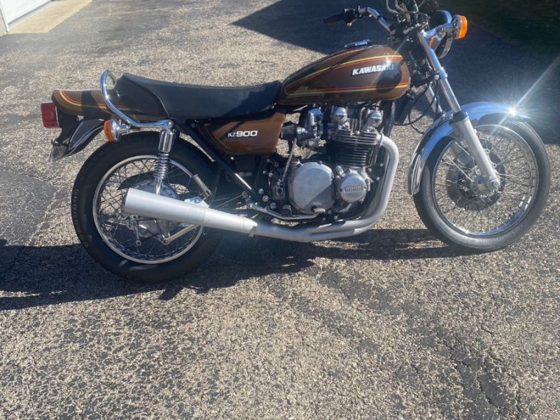
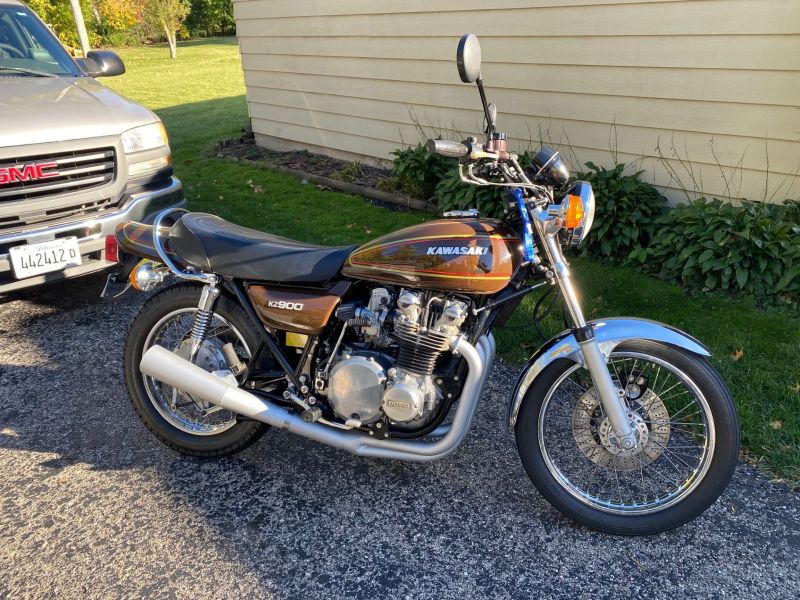
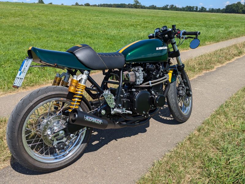
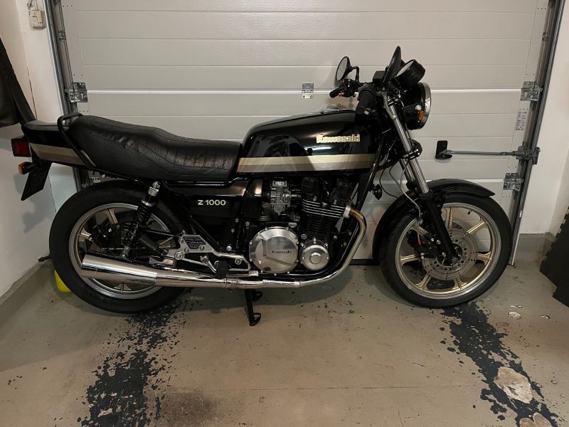
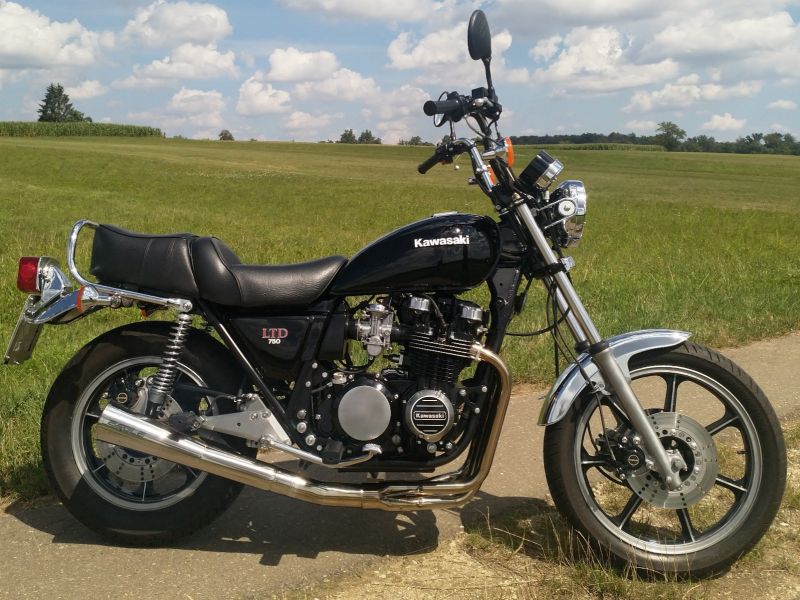
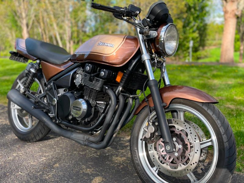
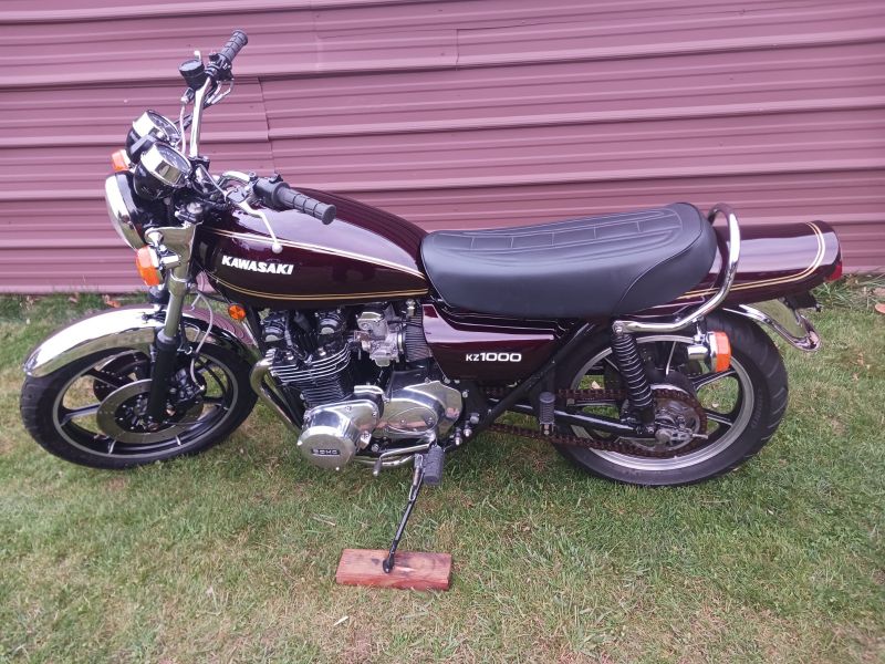
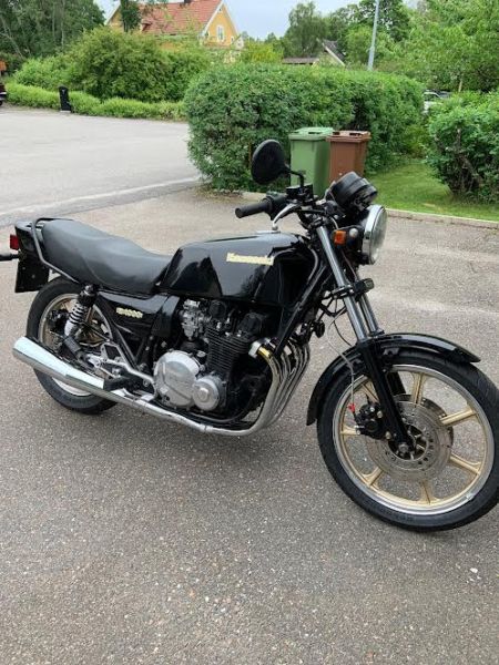
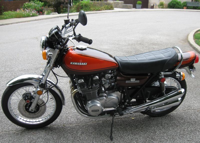
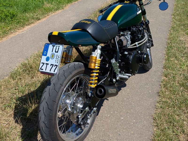
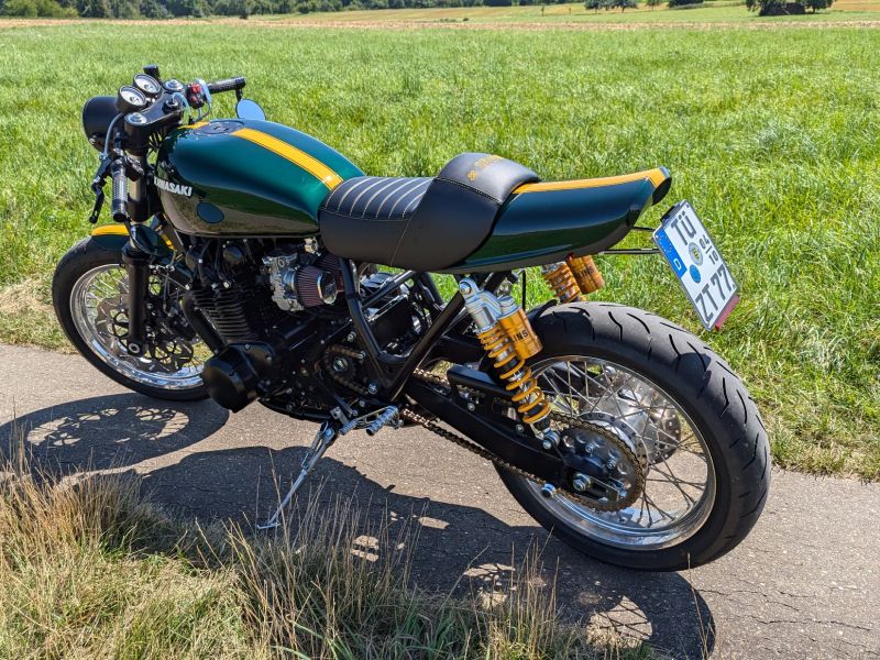
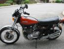
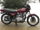
KZR's Bikes of the Month for 2024
EM40-80600 Ignition Switch For 1979 KZ650B3 - Electrical Surgery?

More
08 Jan 2021 09:26 #841357 by CMcAuliffe
Picked up the Z1 Enterprises switch to replace the old, damaged ignition in my late production (Dec 1979) KZ650. The Z1 site states: "The 79 had a unique 5-pin configuration. This switch WILL work but may require a little electrical "surgery". REFER to a wiring diagram for assistance."

My 79 has a six-pin connector, as well as an additional brown wire that goes off on its own to various components according to the Clymer manual (page 299). Also, while the connector wire colors match fairly well between the old and new switch (I have a brown wire on the new that takes the place of the yellow on the old), the pattern where it connects to the switch isn't that close. There are also 2 extra pins on the new connector. Nor can I make sense of the continuity between posts that I get on the new switch to try to replicate the wiring pattern on the old.

Has anyone had the occasion to re-wire an EM40-80600 for a 79? Does anyone have a wiring diagram of the EM40-80600 similar to the one in the Clymer manual that shows which wires are lit up during the "run" or "park" positions?

Please Log in or Create an account to join the conversation.

More
08 Jan 2021 10:07 #841361 by Mikaw
You need to find a wiring diagram that includes a connection Schematic like the one shown in the red box of photo included. It will help you make your swap. Sorry I can’t locate one. Hopefully martin_crs or 650ed will see this. They are very good with you bike.


1976 KZ 900 A4 kzrider.com/forum/11-projects/613548-1976-kz-900-a4
1976 KZ 900 B1 LTD
1978 KZ 1000 B2 LTD
1980 KZ 750 E1
Kowledge Speaks, But Wisdom Listens.
Jimi Hendrix.
Attachments:

Please Log in or Create an account to join the conversation.

  • gd4now
  • Offline
  • User
  • Denco where did you go?
More
08 Jan 2021 10:44 - 08 Jan 2021 10:47 #841363 by gd4now
Here is a wiring diagram for the B3 C3 models. I have also included a text doc of the keyed switch with the number of wires on each and part#s.

27005-083
4 leads on switch - 4 pin connector
KZ650-B1 (1977)

27005-5001
6 leads on switch - 6 pin connector
KZ650-B2 (1978)
KZ650-B2A (1978)
KZ650-C1 (Custom) (1977)
KZ650-C2 (Custom) (1978)
KZ650-D1 (SR) (1978)
KZ650-D1A (SR) (1978)

27005-5007
7 leads on switch - 6 pin connector and single wire
KZ650-B3 (1979)
Kz650-B4 (1980)
KZ650-C3 (Custom) (1979)
KZ650-C4 (1980)
KZ650-D2 (SR) (1979)
KZ650-D3 (SR) (1980)
KZ650-D4 (SR) (1981)
KZ650-E1 (LTD) (1980)
KZ650-F1 (1980)

several part numbers depending upon where sold 27004 with one of the following 5123, 5124,5151,5152,or 27004 with one of thhe following 5024,5026
7 leads on switch - 6 pin connector and single wire
KZ650-F2 (1981)
KZ650-F3 (1982)
KZ650-F4 (1983)

27005-5024 (supersceeded 27005-5015 27005-5017 27005-5027 27005-5035)
7 leads on switch - 6 pin connector and single wire
KZ650-H1 (CSR) (1981)
KZ650-H2 (CSR) (1982)
KZ650-H3 (CSR) (1983)


1977 KZ650 B1
Pods and Denco header


OLD KAW OWNERS SMILE ALOT

Attachments:
Last edit: 08 Jan 2021 10:47 by gd4now.

Please Log in or Create an account to join the conversation.

More
08 Jan 2021 12:34 - 08 Jan 2021 12:35 #841372 by 650ed

CMcAuliffe wrote: Picked up the Z1 Enterprises switch to replace the old, damaged ignition in my late production (Dec 1979) KZ650. The Z1 site states: "The 79 had a unique 5-pin configuration. This switch WILL work but may require a little electrical "surgery". REFER to a wiring diagram for assistance."

My 79 has a six-pin connector, as well as an additional brown wire that goes off on its own to various components according to the Clymer manual (page 299). Also, while the connector wire colors match fairly well between the old and new switch (I have a brown wire on the new that takes the place of the yellow on the old), the pattern where it connects to the switch isn't that close. There are also 2 extra pins on the new connector. Nor can I make sense of the continuity between posts that I get on the new switch to try to replicate the wiring pattern on the old.

Has anyone had the occasion to re-wire an EM40-80600 for a 79? Does anyone have a wiring diagram of the EM40-80600 similar to the one in the Clymer manual that shows which wires are lit up during the "run" or "park" positions?


I very seriously doubt that your bike is 1979 model. Any Kawasaki bike built in December 1979 is a 1980 model. Try to equate the same scenario to cars. No car builder would wait until 1980 to start building 1980 model cars. If they did the dealers wouldn't have any new car inventory to sell in January. Bikes are the same. So you need to buy parts for the 1980 model not the 1979 model bike. Ed

1977 KZ650-C1 Original Owner - Stock (with additional invisible FIAMM horn)
Last edit: 08 Jan 2021 12:35 by 650ed.

Please Log in or Create an account to join the conversation.

More
08 Jan 2021 17:05 #841390 by CMcAuliffe
Frame number is KZ650B 533166, Engine number is KZ650BE 115937. From what I found online, of course with a grain of salt, these are 1979 numbers. I'm not married to that idea, just going on what I've found so far absent some factory information.
I I have the electrical diagram of what it is I'm supposed to have in the Clymer Manual (1977-83).
What I need to know is my starting point in the EM40-80600, or better yet, what changes were made to the switch to make it work.
I've contacted Z1, but haven't heard back and I'm antsy to try to crank this over.
Only 28,000 miles on it!

Please Log in or Create an account to join the conversation.

More
08 Jan 2021 19:08 #841401 by 650ed
Take a look at the links below. It looks like your bike is a 1980 model. Most likely a KZ650-B4.

kzrider.com/forum/5-chassis/536286-kz650...ne-number-confusions

models.kz650.info/

1977 KZ650-C1 Original Owner - Stock (with additional invisible FIAMM horn)

Please Log in or Create an account to join the conversation.

More
08 Jan 2021 21:52 #841409 by F64
Send a picture of the back of the new switch and back of the old switch.
Then send a pict of new connector vs old connector.
I have a feeling you may have to move some pins around on the new connector or splice the old connector to the new switch.

81-KZ440-D2.
Louis Dudzik's GM HEI ignitor conversion installed 2015 s3.amazonaws.com/gpzweb/Ignition/GPZgmHEImod.html
Motogadget m-unit blue installed 2017.
LIC, NY

Please Log in or Create an account to join the conversation.

  • gd4now
  • Offline
  • User
  • Denco where did you go?
More
09 Jan 2021 09:32 #841428 by gd4now
Do you have a VOM (volt, ohm, meter)? If yes then you can test the new switch as to what is hot once you turn the key to the on position and use the wiring diagram to figure out what if any changes need to be made in the connector.

1977 KZ650 B1
Pods and Denco header


OLD KAW OWNERS SMILE ALOT

Please Log in or Create an account to join the conversation.

More
09 Jan 2021 11:30 #841435 by CMcAuliffe
I reassembled the old switch to check what gets lit and when. I checked it against the new and wrote up a wiring diagram for both. It seems the new switch would still keep the extra wire hot in the second key position.
Otherwise, it looks like I can just add the wire to the empty spot on the new and be done with it.

Attachment not found


What's the second position for, anyway?

Please Log in or Create an account to join the conversation.

More
09 Jan 2021 11:38 #841438 by Mikaw
It parking. Allows the tail lights and running lights to be on without power the the coils...


1976 KZ 900 A4 kzrider.com/forum/11-projects/613548-1976-kz-900-a4
1976 KZ 900 B1 LTD
1978 KZ 1000 B2 LTD
1980 KZ 750 E1
Kowledge Speaks, But Wisdom Listens.
Jimi Hendrix.
Attachments:

Please Log in or Create an account to join the conversation.

More
14 Jan 2021 17:12 #841710 by CMcAuliffe
The six-pin connector on the EM40 fits my application perfectly – all colors of the connector fit except the yellow wire on the original is brown on the EM40.
The original had a 7th, brown wire. I used a voltmeter to check for continuity on my original switch (and to verify the Clymer Manual) and then on the EM40.
It looked like all I had to do was take the brown wire from the original and place it on the empty terminal of the EM40. I wasn’t sure what I could do about the park position – I figure I’d worry about it only if I had to.
Popped everything in place, dropped in a new battery and: front parking lights, headlight, neutral indicator & Brake light failure light came on – as soon as the battery was hooked up – Key was in the OFF position.
Turning the key did nothing. The lights I mentioned stayed on, nothing else. Not in the “ignition” position, or the one after that.
Ideas?
Attachments:

Please Log in or Create an account to join the conversation.

More
15 Jan 2021 16:05 #841752 by jwfels
Hi there, backfeed, all the loads on switch, wires are pretty much common, lights and ignition, you are feeding the battery lead to a load connection so everything lights up when you connect battery, the ignition switch is basically a big single pole switch with multiple load points, read all points on switch with VOM on continuity, with switch off, should see a bunch that read continuity and one that doesn't, turn key on, and all should read, that be used for incoming 12+, check fuse for 12+ color (white?) main feed , reconfigure connectors as needed, good luck.

Z1A AND 81 650

Please Log in or Create an account to join the conversation.

Powered by Kunena Forum

If you like KZR Please consider making a donation. Thank you.

KZRider is free, but not without cost.

Please consider chipping in a few bucks to help cover the cost of running the KZR servers.