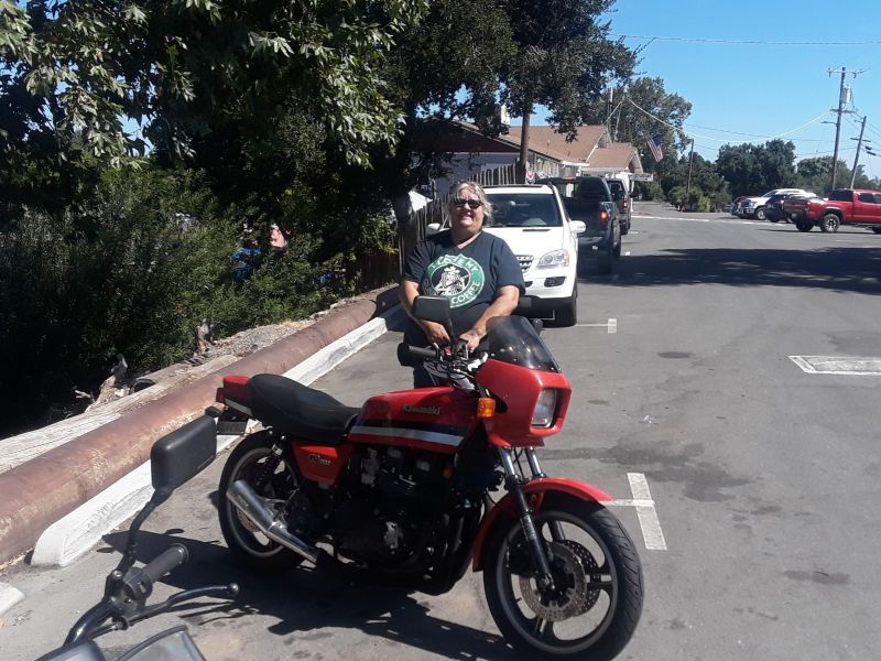
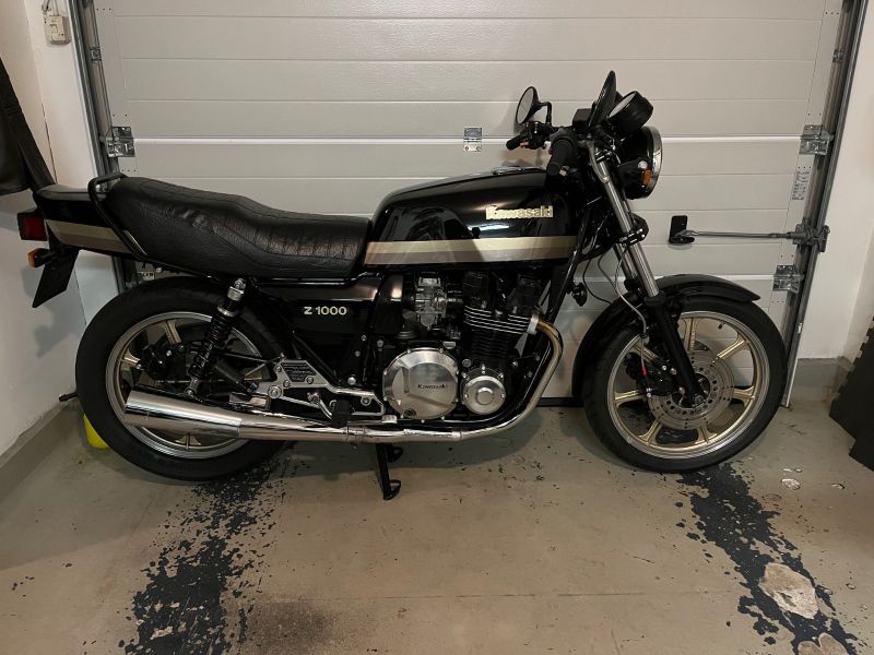
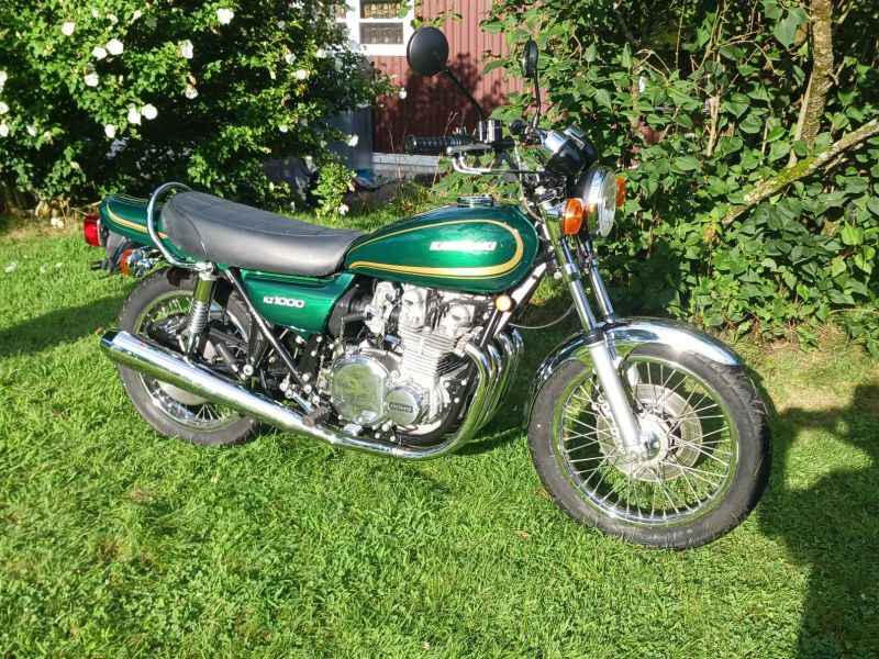
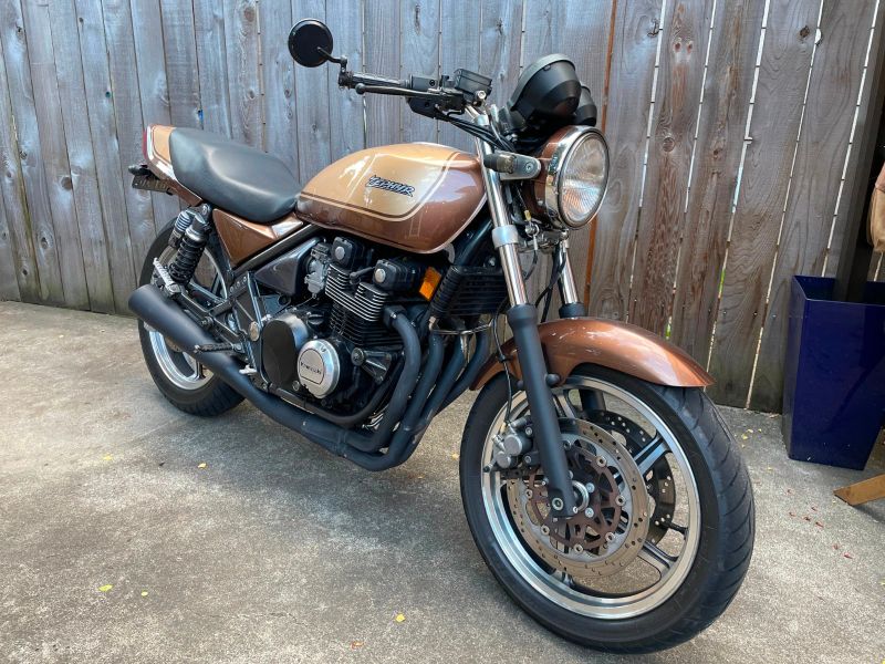
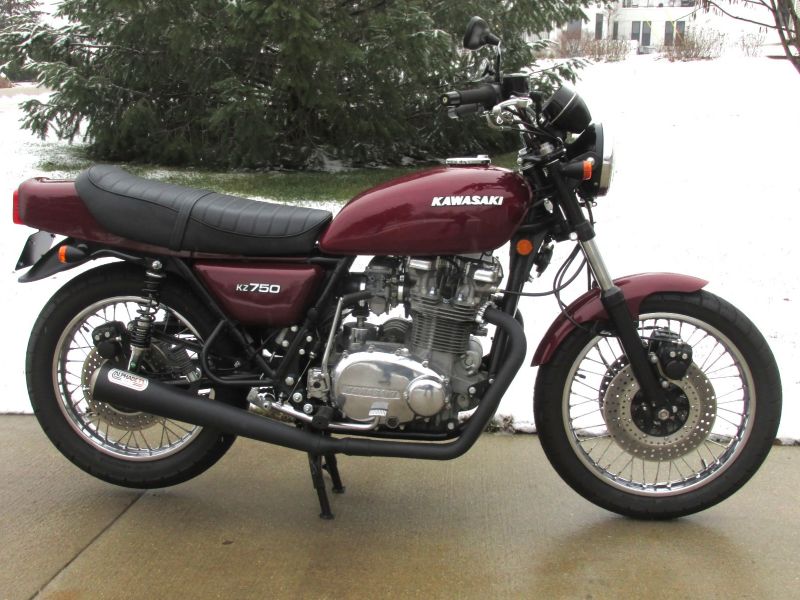
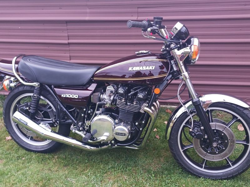
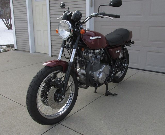
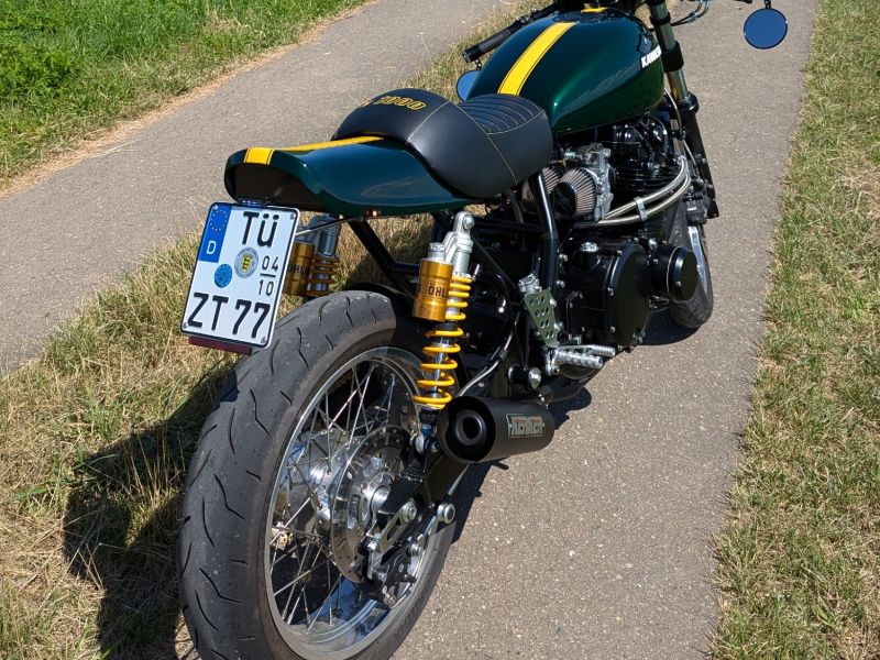
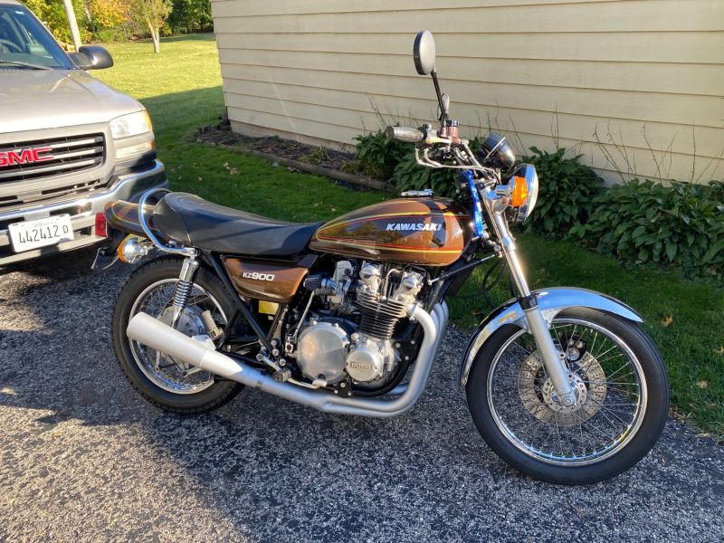
KZR's Bikes of the Month for 2024
KZ4 Wiring
  • Dirty0ldMan.
  • Topic Author
  • Offline
  • User
More
24 Jun 2019 13:56 - 24 Jun 2019 13:59 #806353 by Dirty0ldMan.
KZ4 Wiring was created by Dirty0ldMan.
Have an old bike I am trying to get running
I believe it's a KZ400 engine mounted in a KZ440 frame

Engine Stamp:

I drew a diagram of how I first attempted to wire the bike based on some images I found online


When I jump 12v straight to the starter motor it does try to turn over.

Plugged in the wiring snake to the positive terminal of my battery and the wires started to melt from the Kill Switch/Ignition Button.


I was using an On/Off switch to act as a Key switch would with a 20AMP fuse separating it from the battery.


Starter Solenoid Right Side Pin is connected straight to the Pos+ battery terminal -Constant 12v with no fuse-
The Starter Solenoid Left Side Pin is connected to the Starter Motor via factory ring terminal that comes from the starter.

From the starter Solenoid protrude 2 wires: 1 black, 1 red/yellow.
Black Wire: connected to the Ignition FIRE button on the right side handlebar control.
Red/Yellow Wire: connected to the the Yellow/Red wire to power the Coils.

Coils also have a Blue wire connected to the engines Points.
Kill Switch: is grounded from the Batterys Negative Terminal and powered through the On/Off Switch and 20 AMP fuse.

Regulator* has 5 wires
Yellow x3: connected to the engines copper spool from 3 Yellow Wires and a factory connector
White: I grounded from the negative terminal of the battery
Black: I have connected to the POS+ battery terminal before the 20AMP fuse


The bike also has a Transistor Igniter pictured here, I was unsure of it's function in the system and left it out altogether.


My current goal is to get the engine running from the Started Button/Starter Motor.
I can figure out lighting, turn signals, and the horn later down the road

Any advice is much appreciated
Thanks //
Last edit: 24 Jun 2019 13:59 by Dirty0ldMan..

Please Log in or Create an account to join the conversation.

More
24 Jun 2019 15:24 - 24 Jun 2019 15:33 #806355 by loudhvx
Replied by loudhvx on topic KZ4 Wiring
I don't think that is a regulator. It looks like a rectifier only. We would need to know more about the engine to know what type of regulator you need.
We need to see the alternator cover, that is the left side of the motor. And we need to know how many yellow wires are coming from your stator.

I believe you should disconnect the rectifier as you have it described. White would more likely be positive and black would more likely be ground on a Kz rectifier. As you describe it, it is wired as a short and might go up in smoke and will definitely melt wires. Kz's don't use wiring colors the same as a Honda (which I assume is why you connected black to the positive terminal). Their color convention is different.

The wiring in that diagram is unconventional to Kz's. Most/all Kz's switch the positive side of the starter-solenoid's coil rather than grounding the negative side.

Also, you show the kill switch wired as a start button. That would not be wise. Use the starter button instead, to operate the starter. The kill switch is meant to power the ignition.

I'm not sure why you show a ground on the toggle switch, but if it's a switch contact, it will blow the main fuse under certain configurations and could start to melt wires.

There are so many irregularities in that diagram I think it needs to be drawn over from scratch.
Once you know which alternator you have, and decide on where to get a new regulator/rectifier, I can draw a new diagram.
Last edit: 24 Jun 2019 15:33 by loudhvx.

Please Log in or Create an account to join the conversation.

  • Dirty0ldMan.
  • Topic Author
  • Offline
  • User
More
24 Jun 2019 17:57 #806370 by Dirty0ldMan.
Replied by Dirty0ldMan. on topic KZ4 Wiring
I believe it's an excited field alternator, it has 3 yellow wires that feed into a Female connector


The rectifier is stamped S4T-05 and has 3 yellow wires to a corresponding Male connector. As well as a black and white wire

Attachments:

Please Log in or Create an account to join the conversation.

More
24 Jun 2019 18:21 - 24 Jun 2019 18:26 #806372 by loudhvx
Replied by loudhvx on topic KZ4 Wiring
Ok, then you will need a regulator to control the field coil, and a rectifier to rectify the stator output.
That regulator will have 3 wires, brown, green, and black.
Brown is switched 12v and is on whenever the ignition is on.
Green is the power to the field coil which the regulator will control.
Black is ground.
You can get one from OregonMotorcycleParts.com
here's a link. You would want the VR3-KZ
www.oregonmotorcycleparts.com/vregulators.html

The field coil will also have a ground wire.

The rectifier is like what you have, but the one you have might be burned out due to reverse-polarity.
3-phase rectifiers can be had very cheaply, though.
3 yellows are the AC input.
White is output to the battery.
Black is ground.

You could also get a combination reg/rec which is basically the two separate parts in one unit.
In this case, you would want VRREM7-KZ.
www.oregonmotorcycleparts.com/Reg_rec_units.html
Last edit: 24 Jun 2019 18:26 by loudhvx.
The following user(s) said Thank You: Dirty0ldMan.

Please Log in or Create an account to join the conversation.

More
25 Jun 2019 13:34 #806414 by gavroyer
Replied by gavroyer on topic KZ4 Wiring
I don't think you have an excited field alternator. That sounds like a regular permanent magnet 3-phase alternator to me. An excited field alternator will need at least four wires, and more likely five, just for the alternator. (Two-three for the output, and two for the field).

Your engine-frame assessment appears to be correct. That is definitely a KZ400 engine, and if it has electronic ignition then it's likely a KZ440 (either 81 or 82, as 1980 KZ440s still had points). If you don't want the ignition, I'll gladly take it off your hands. =D

1980 KZ440-A1 LTD
The following user(s) said Thank You: Dirty0ldMan.

Please Log in or Create an account to join the conversation.

More
25 Jun 2019 15:05 - 25 Jun 2019 15:12 #806427 by loudhvx
Replied by loudhvx on topic KZ4 Wiring

gavroyer wrote: I don't think you have an excited field alternator. That sounds like a regular permanent magnet 3-phase alternator to me. An excited field alternator will need at least four wires, and more likely five, just for the alternator. (Two-three for the output, and two for the field).

Your engine-frame assessment appears to be correct. That is definitely a KZ400 engine, and if it has electronic ignition then it's likely a KZ440 (either 81 or 82, as 1980 KZ440s still had points). If you don't want the ignition, I'll gladly take it off your hands. =D


All he really needed to show us was the alternator cover. Notice the 3 allen screws in a triangle pattern. On the Kz400 and Kz650 (and not necessarily other Kz's) that indicates an excited field alternator. As mentioned, the rectifier he shows is NOT a regulator. I suspect some previous owner never got that charging system working.

I forgot I made this graphic long ago... I'll quote from another similar post on Kzrider

loudhvx wrote: The 1976 400 (and other 400's) motor, from what I remember uses an alternator cover with a slightly different bolt pattern from the newer motors, so you can't swap covers, and the cover is needed to hold the field coil. The later motors don't use a filed-coil type alternator.

I found an image I created a few years ago.


And here are some quick notes I made for myself back then (hopefully it is correct):
PM means permanent-magnet as opposed to the type that uses an electro-magnet, also known as field coil.

The 400's (except for the B, C, and H) use excited field alternator with cover 14031-1007-80. This spans over many years and overlaps with the PM alternator years.

The 400 B and H use PM alternator with cover 14031-1023.
The 400 C uses same PM alternator with cover 14031-1001-80.

Some 440's some use PM alternators with cover 14031-1023.
Some 440's use the same PM alternator with cover 14031-1083.

The two cover types won't interchange on a motor, and the two types of alternators require different cover types.
The E field cover has 10 holes.
The PM cover has 11 holes, and they are in different places.

The ends of the cranksharft may also be different, which would make the swap very difficult.

These notes are not complete!
Need complete list of stator, flywheel, and cover numbers.

Last edit: 25 Jun 2019 15:12 by loudhvx.
The following user(s) said Thank You: Dirty0ldMan.

Please Log in or Create an account to join the conversation.

  • Dirty0ldMan.
  • Topic Author
  • Offline
  • User
More
17 Jul 2019 16:21 #807684 by Dirty0ldMan.
Replied by Dirty0ldMan. on topic KZ4 Wiring
Yeah Loud I based findings of the excited field alternator off of your diagram. I also got hold of a rectifier with the brown black and green connectors you described, If you could draw me a wiring diagram I would really appreciate it

Please Log in or Create an account to join the conversation.

More
18 Jul 2019 07:21 - 18 Jul 2019 07:59 #807725 by loudhvx
Replied by loudhvx on topic KZ4 Wiring
The regulator has brown, black, and green.
The rectifier has 3-yellow, black, and white.

I posted it on page 23 of the mattylight thread.

www.kzrider.com/forum/4-electrical/17274...ght?start=440#807723
Last edit: 18 Jul 2019 07:59 by loudhvx.

Please Log in or Create an account to join the conversation.

Powered by Kunena Forum

If you like KZR Please consider making a donation. Thank you.

KZRider is free, but not without cost.

Please consider chipping in a few bucks to help cover the cost of running the KZR servers.