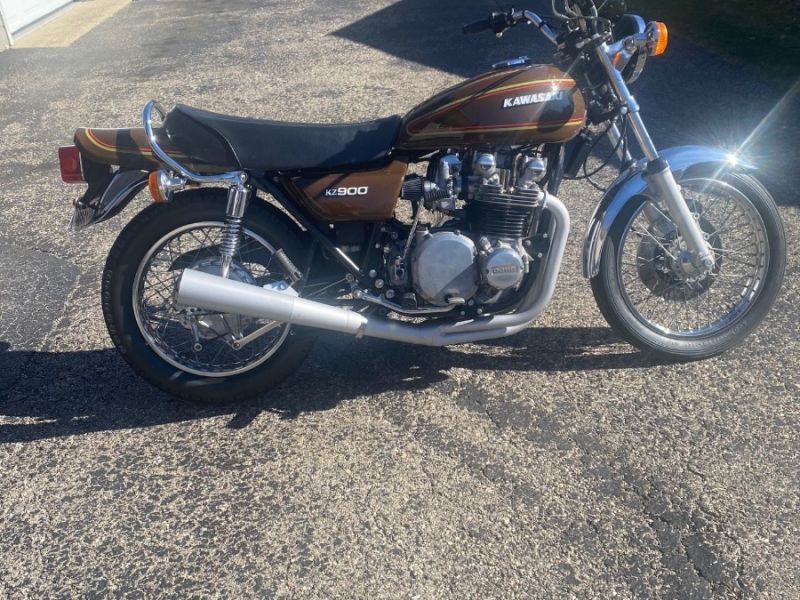
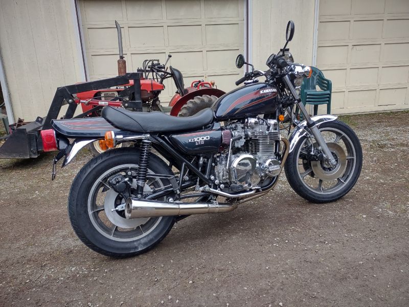
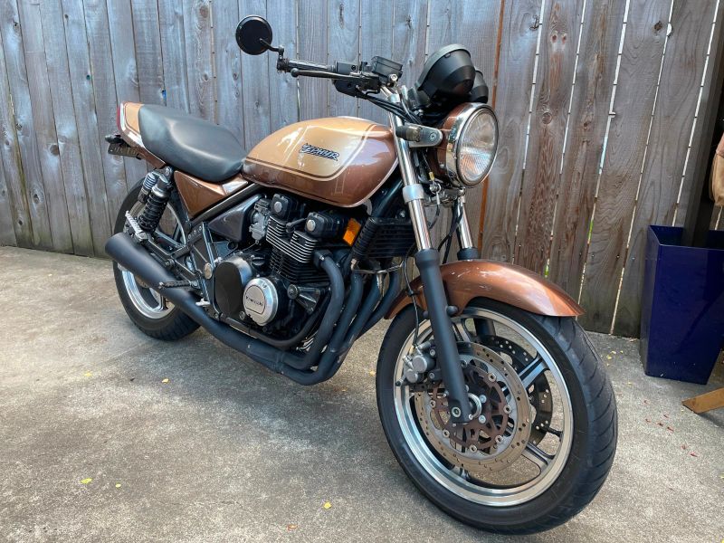
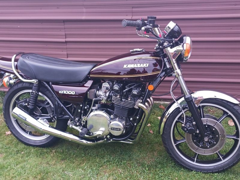
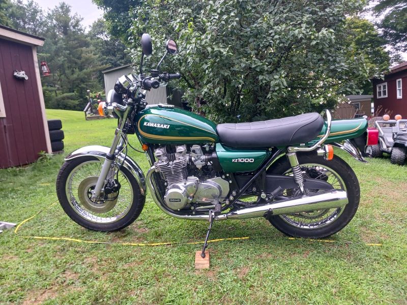
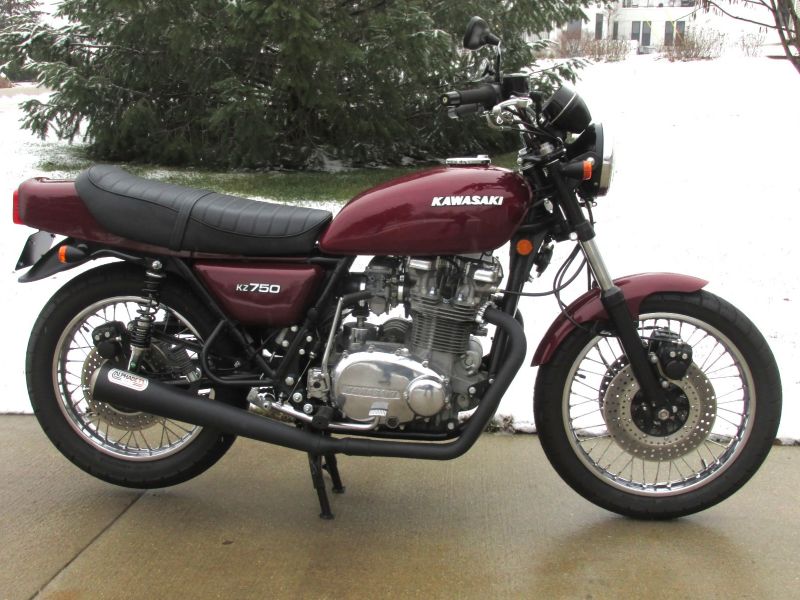
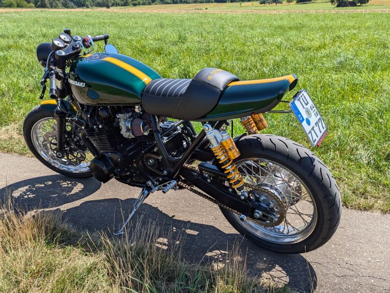
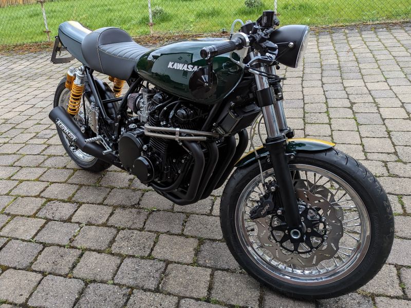
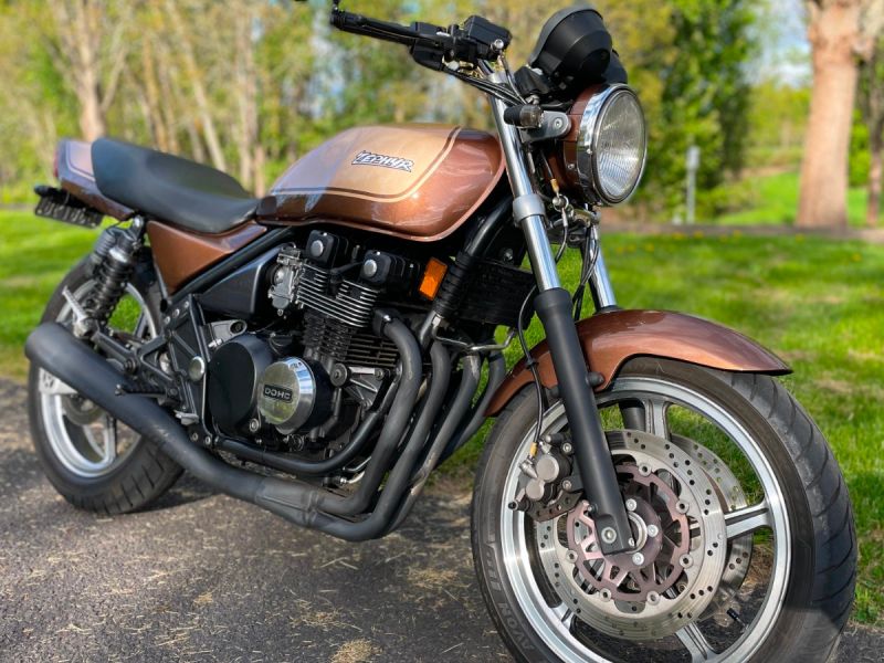
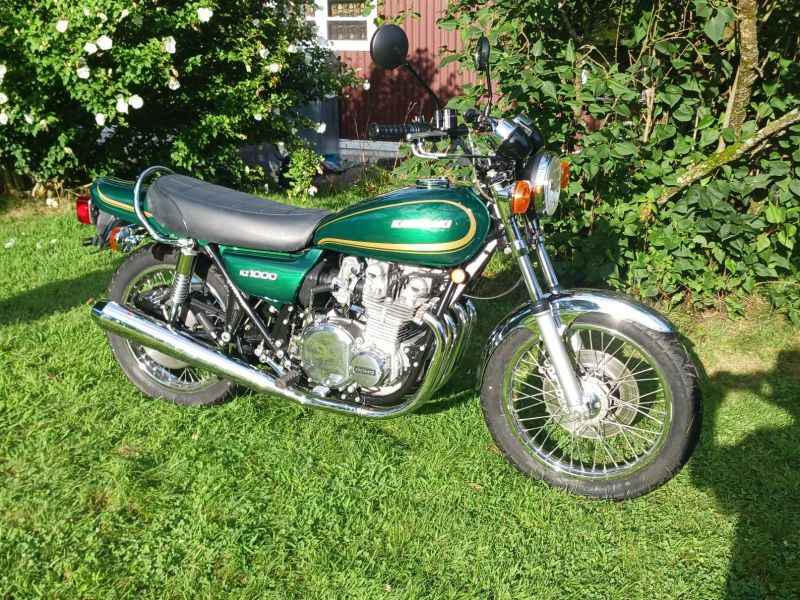
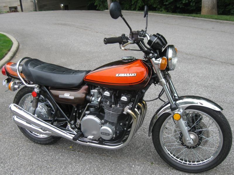
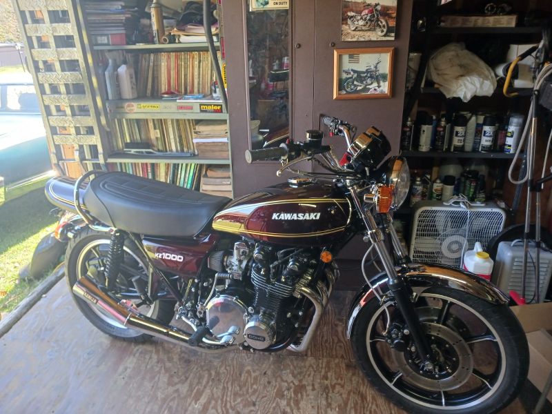
KZR's Bikes of the Month for 2024
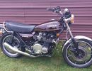
KZ1000 Advancer.

More
17 Feb 2006 18:58 #24590 by rstnick
KZ1000 Advancer. was created by rstnick
Can someone confirm for me if the cam in this pic is at the right position and not turned 180*?

This is a '79 KZ1000 advancer I believe. The high point on the cam being at 9:00 o'clock in the pic with the # on the back plate at approx. 10 ~ 11.
.

Rob
CANADA

Need a key for your Kawasaki? PM me

1978 KZ650 C2, 130K kms, Delkevic ex, EI, CVK32, PMC easy clutch, ATK fork brace, steering damper, braced swingarm, ZRX shocks, 18" Z1R front wheel.
2000 ZRX1100
2011 Ninja 250R - Wife's
2005 z750s (aka GPz750)
1978 KZ1000 project
Attachments:

Please Log in or Create an account to join the conversation.

More
17 Feb 2006 20:27 #24606 by Sandy
Replied by Sandy on topic KZ1000 Advancer.
Yes,Rob...that is the correct set-up,and not 180 out,Bud.
I have both style set-ups(points and electronic...both factory,too) and on My points set-up...the lobe area on the cam also points in that same direction.And the electronic set-up I have is exactly like Yours.
So You can rule the "180 out"...out!B)

Post edited by: sandy, at: 2006/02/18 00:29

1977 KZ1000 A-1

Please Log in or Create an account to join the conversation.

More
17 Feb 2006 20:54 #24608 by loudhvx
Replied by loudhvx on topic KZ1000 Advancer.
Rob, I think you need to verify that the T mark lines up when your #1 cyl is at top dead center. If not, then you need to scribe in your own marks for TDC and firing position (and advance position).

There are a lot of variables to consider.


The advancer relative to crank.
The engine's timing pointer relative to the advancer.
The rotor-arbor relative to the advancer.
The iron slug relative to the rotor-arbor. (It's pressed on and can be moved.)
The pickup locations relative to the engine.

Some or several of these can be 180 out.
Then the wiring can always be 180 out as well.

In your situation, these all need to be checked. It can all be checked statically... Before blowing anything up ;)

By the way, did you verify the advance angle matches the 650's advancer? Just curious.

Post edited by: loudhvx, at: 2006/02/18 00:03

Please Log in or Create an account to join the conversation.

More
18 Feb 2006 16:17 #24741 by rstnick
Replied by rstnick on topic KZ1000 Advancer.
Sorry Lou, I need some help understanding some of your points:

The advancer relative to crank.

The pin/key on the crank is slotted into the advancer. Is this what your refering to?

The engine's timing pointer relative to the advancer.

Sandy's confirmed this position above.

The rotor-arbor relative to the advancer.

Should I be comparing where the pin/key slot is between the 650 and 1000?

The iron slug relative to the rotor-arbor. (It's pressed on and can be moved.)

Don't quite understand this.

The pickup locations relative to the engine.

I do have slotted holes on the backplate for adjustment. Your first line covers this, correct?

you need to verify that the T mark lines up when your #1 cyl is at top dead center

By the way, did you verify the advance angle matches the 650's advancer?

This is comparring the backside where the pin/key location is right?

Again sorry for my ignorance, but like you said, I need to varify all this before I start her up. Or should I say, Try.

Rob
CANADA

Need a key for your Kawasaki? PM me

1978 KZ650 C2, 130K kms, Delkevic ex, EI, CVK32, PMC easy clutch, ATK fork brace, steering damper, braced swingarm, ZRX shocks, 18" Z1R front wheel.
2000 ZRX1100
2011 Ninja 250R - Wife's
2005 z750s (aka GPz750)
1978 KZ1000 project

Please Log in or Create an account to join the conversation.

More
19 Feb 2006 16:08 #24973 by loudhvx
Replied by loudhvx on topic KZ1000 Advancer.
Here's what you need to cover.

1) The advancer relative to crank.
2) The engine's timing pointer relative to the advancer.
3) Timing characteristics of the advancer.
4) The rotor-arbor relative to the advancer.
5) The iron slug relative to the rotor-arbor. (It's pressed on and can be moved.)
6) The pickup locations relative to the engine.

Well, I don't think you'd be able to verify this stuff from photos. You want to be accurate to within a degree or 2.

Let's start at the engine. The engine has a pointer cast into it. The advancer has marks scratched into it. When the T mark on the advancer lines up with the pointer, the 1 & 4 piston should be at top dead center. You need to verify this.

Put a vise grip on the alternator bolt. This is so there is no slop when turning the crank. Take out the plugs so you are not fighting compression. Put a stick of some sort into #1 plug hole and turn the crank to find TDC. Since there can be play in the bearings, you need to find the point where the piston stops moving up. Ignore the point where the piston starts moving down. Bring the piston up and note where the visegrip is when the piston stops moving. Do the same thing again, but by turning the crank the opposite way. Now you have two points where the piston stopped moving. If you have tight bearing tolerances, the two points should be very close together. The position in the middle of the two points is TDC. Do this several times until you get consistent results. Don't turn the engine backward for any great distance. These are very small movements you should be doing.

The T mark on the advancer should line up with the pointer on the engine. This verifies the advancer's marks can be used on your engine. If it didn't line up, you'd have to make your own timing marks on the advancer.

That takes care of the first two things on the list.

#3 is tougher, but if you have some specs on the bike the advancer came from it would make it easier. You need to know the difference between the static advance (advance at idle) and the full advance (at high Rpm). This difference tells you how much the advancer will advance the timing. It is the amount of angle you can rotate the cam on the advancer. You want it to be the same as the one you took off your bike. This will take some very careful measurement. If the amount of advance is different, you correct it by bending the stop tabs. Those are the tabs that stop the arm movement. if this is changed, the full-advance scratch marks on the advancer will no longer be valid. You can put a punch mark in the relevant location if you want to verify the full advance using a strobe later on. To put the punch mark in the right place will take some very careful measuring, maybe some geometry or a protractor. Hopefully, the advance angle will be the same.

You also want the advance arms to be the same weight and shape so you'll know they'll behave the same. If they look reasonably the same shape and are the same thickness as the ones off the 650, then you'll be fine (you may just be able to use the 650 arms if need be). The springs need to be the same, but you don't know if your old stock springs are good. This can be checked after the bike is running by checking the amount of advance per rpm (using a tach and strobe) . There should be details in the manual for this.

I guess we need to clear up terminology. What I call the slug is the cast-iron-looking pointer piece. It is pressed onto the hollow tube I call the arbor. Together, they make up the rotor. The rotor rotates on the advancer's shaft. It's rotation is controlled by the movement of the advance-arms.

#4, 5 and 6 are often not in agreement which forces people to make the timing plate mounting holes into ovals to allow for a wider range of adjustment. The net affect of 4,5 and 6 can be checked at one time, statically. If #1, 2 , and 3 have been checked, then assemble everything. Rotate the crank until the F mark (for 1 & 4) is lined up with the cast-in pointer on the engine. The center of the slug's pointer should just barely be passed the center of the pickup with the black and blue wires on it. (This pickup should be toward the back of the motor when the pickup plate is installed. The yellow-red pickup is toward the front. If not, then maybe the 1000 is different from the 550/650/750.)

If the slug pointer is not pointing toward the black/blue pickup, it should be flipped 180 degrees. If the point is in the right direction, but not quite close enough to be exact, and the timing plate (pickup plate) can't be rotated any further, there are two ways to compensate. You can cut the groove on the timing plate to allow for more adjustment, or you can carefully pull the slug off the arbor and press it back on in the right place. You need a decent arbor-press to do it right (this means without marring or breaking the slug. A chip in the slug will cause mis-fires), but it's not presssed on real tight.

This should be it. The blu-black pickup should feed the ignitor to control the coil with the black wire, which will feed spark-plugs 1 and 4. The yellow-red pickup should feed the ignitor to control the coil with the green wire, which will feed spark-plugs 2 and 3. At least, that is how it is on the 550/650/750 family ignitions. If wires are swapped, it's as if they are "180-out".

Many of these things can be "180-out". If an even number of things are "180-out", they cancel each other and it should still run.

Please Log in or Create an account to join the conversation.

More
19 Feb 2006 18:42 #25011 by rstnick
Replied by rstnick on topic KZ1000 Advancer.
Thanks for the explanation. I saved and printed it off. I will check all of it and let you know how it turns out.

Rob
CANADA

Need a key for your Kawasaki? PM me

1978 KZ650 C2, 130K kms, Delkevic ex, EI, CVK32, PMC easy clutch, ATK fork brace, steering damper, braced swingarm, ZRX shocks, 18" Z1R front wheel.
2000 ZRX1100
2011 Ninja 250R - Wife's
2005 z750s (aka GPz750)
1978 KZ1000 project

Please Log in or Create an account to join the conversation.

Powered by Kunena Forum

If you like KZR Please consider making a donation. Thank you.

KZRider is free, but not without cost.

Please consider chipping in a few bucks to help cover the cost of running the KZR servers.