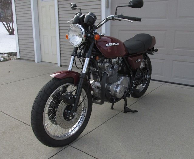
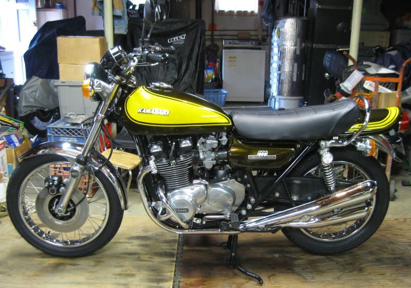
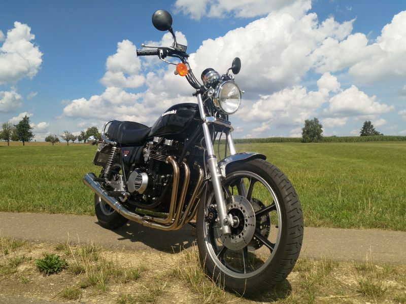
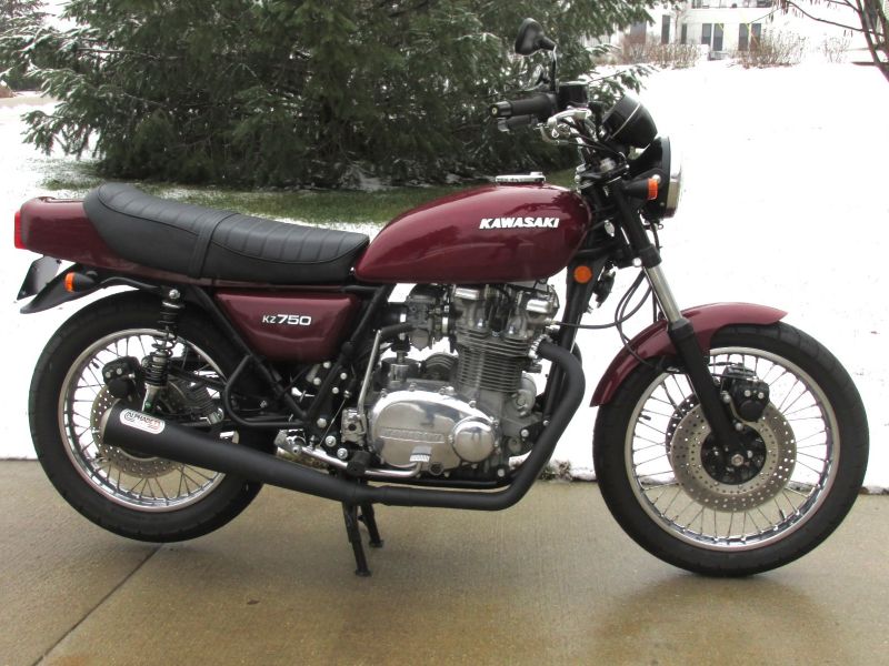
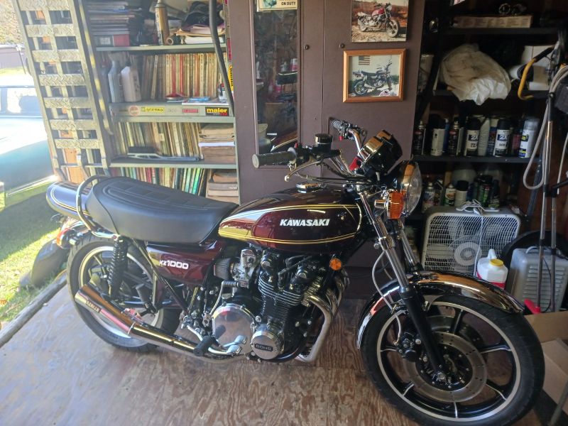
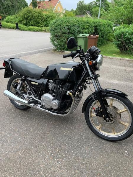
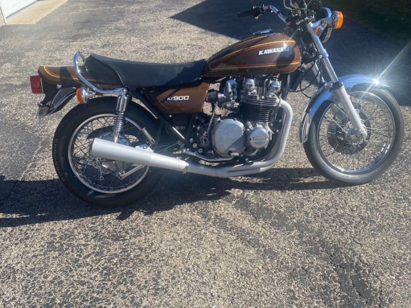
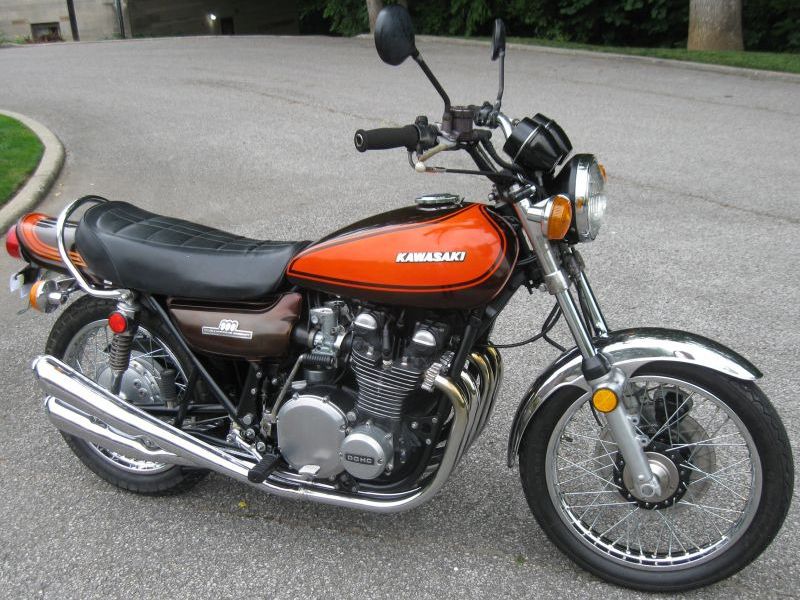
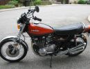
I'll post here what I've obtained from "Wired George" about improving the ignition coil input voltage on these older Z's and KZ's. As the article states, many people confuse carb problems with weak spark.
Re-powering Ignition Coils To Get Full Power
By Wired George (his website is
www.wgcarbs.com
)
Condition/Symptoms:
A problem common to MOST vintage motorcycles is often characterized by hard starting, rough running, backfiring, and sooty or fouled spark plugs.
What most people recommend?
Since the plugs are sooty or fouled, the air/fuel mixture is often singled out as the culprit, in other words, your carburetors' air/fuel mixture is too rich. You will be told to use smaller main jets, move the clips on your jet needles up or fiddle with your mixture screw or pilot screws. These recommendations MAY lessen the plug fouling and other symptoms but may also have no effect, other than cause tuning problems which ultimately only make matters worse.
OK, have you tried these things to fix the "rich" problem?:
· cleaned air filter or pods
· rebuilt carburetors and know that their innards are clean and properly jetted
· know there is no crud in the bowls or being passed from the tank
· carburetors have correct float levels
If you have checked these things and the problem with sooty or fouled plugs is still there, then your problem may NOT be carburetor induced! Consider that three things are necessary for complete combustion.
correct air/fuel mixture
good compression
good spark
If you are confident your air filter(s) are clean, the carburetors are jetted appropriately, then ensure you have good compression by adjusting your valve clearances. Read the Valve Clearances article in our wg's Tech Stuff Index area. Last, if your ignition components to include, points/condensors, OEM ignitor/pickup coils, plugs, plug wires/caps or coils are old and their condition is suspect, replace them. There are troubleshooting procedures outlined in a Clymer manual or Kawasaki Factory Service Manual which give step-by-step procedures for checking these components functionality.
WHY DO I HAVE A WEAK SPARK WITH GOOD IGNITION COMPONENTS?
The voltage feeding your ignition coils is insufficient to cause the coils to fire a strong spark! This problem is common to almost 100 percent of all vintage motorcycles... Check it out yourself!
Get a multi meter and put the POSITIVE probe on the coil power wire. This wire is attached to a lug on your coil and will be either yellow/red, pink or red (depending on Kawasaki model). Put the NEGATIVE probe on a frame or engine ground. Put the multi meter in VDC scale. Turn the key on with the kill switch in the RUN position. You do not have to start the bike. If you get less than 12 VDC, your coils are being robbed of power. Why? Old wiring, connectors and switches!
The issue is that YOU HAVE A WEAK SPARK due to poor coil voltage and no amount of tuning will rid you of the symptoms or soot/plug fouling. We suggest you power the coils using a separate circuit via a standard automotive relay. Bosch and other electrical component manufacturers produce relays that will work for this application. Relays can be purchased at most auto parts stores and places that install automotive stereos and alarms. You can also purchase relays and pigtails on the web from places like Parts-Express .
These relays have STANDARDIZED number coded connectors. A drawing is supplied at the top of this article which shows how to wire the relay into your bike. After rewiring, your coils will fire a spark as never before. The soot and rough running will be over when you have made this simple modification. The relay can be mounted to the motorcycle frame or battery box.
To perform this modification, buy the following:
12 gauge wire
18-16 gauge wire
soldering iron and light duty rosin core solder
heat shrink wrap (3/16â€)
standard automotive relay (four or five pin)
standard relay pigtail
inline fuse holder rated for 30A
pack of 10A (inline type) fuses
press-in male connector (see the dual-outlet coil connector over your valve cover)
crimp on female lug connectors for 18A wire and 12A wire
cable ties
Need help finding a relay and pigtail? The relay is at the top of the page and a corresponding pigtail is linked towards the bottom... See this link:
www.partsexpress.com/pe/showdetl.cf...tnumber=330-070
Installation Steps:
NOTE: first disconnect your battery!
The relay can be attached to a nut/bolt on your battery box under your seat. The relay has male connectors. While it is possible to use crimp on female connectors attached to the relay male connectors, this type installation WILL oxidize quickly and fail. We suggest using a standard relay pigtail which plugs onto the relay and has 5 wires coming off it that correspond to the connectors on the relay. Connect the relay to the motorcycle and then solder wires to the pigtail. Once all connections to the pigtail are complete, plug the pigtail onto the relay.
Relay Ground Connection #85
Solder / shrink wrap one end of a 18 -16 gauge wire to connect to relay lug # 85 wire on the relay pigtail. Use a piece of wire sufficiently long so that it can be connected to the motorcycle’s main engine ground point. Find this location by tracing the negative battery terminal wire to where it is secured either on the frame or engine. To properly solder a wire to wire connection, join the wires by twisting them together. Warm the joined wire ends with a soldering iron and hold solder on top of these wires until this solder melts and permeates the joined ends; that is, it penetrates through the wires. Once the connection is soldered and cools, pull a piece of shrink wrap over it and melt the shrink wrap with a lighter or heat gun. Install a crimp on “eye†type connector (it should be blue) on the end to be connected to the ground. Remove the bolt securing the main engine ground wire and install the relay wire connector and main ground wire and retighten the bolt. This is the relay GROUND!
Power to Relay #30
Solder / heat shrink one end of a 12 gauge wire to connect to relay #30 pigtail wire. Put about 1 inch of heat shrink onto the free end of the wire and move it towards the relay and out of the way for now. Cut the wire on the inline fuse to make two ends. Put a 10A fuse in the holder and reconnect. Solder the inline fuse end to the 12 gauge wire connected to the relay pigtail. Strip a bit of insulation from the other end of the fuse holder wire and install an “eye†type connector (should be yellow). Loosen the nut that retains the positive battery connection on the starter solenoid and place eye connector end of the wire onto the stud where the nut was removed from and replace the nut and retighten. This is the relay POSITIVE 12 VDC battery connection.
Relay Trigger #86
Find the yellow/red wire that had previously been used to power the coils. It comes out of the wiring harness above the valve cover. This wire terminates in a dual outlet female connector. From this connector, voltage connections are made to both ignition coils. Remove these connections and discard them. Solder / shrink wrap a wire coming from the #86 relay pigtail sufficiently long to reach this connector. Install the press-in male connector and plug the connector into the dual outlet connector coming off the wiring harness above the valve cover. This is the relay TRIGGER. Note that the trigger wire is controlled by the motorcycle kill switch which must be in the ON position for the relay to function.
Power Wires to Coils #87
The last piece to be fabricated is the positive wiring to the coils. From the relay pigtail #87, solder / shrink wrap a length of 18 ga. wire sufficiently long to reach the rear of the coils. At this point, solder / shrink wrap two wires that will each go to the front of one of the coils forming a “Yâ€. Install a blue crimp-on “eye†type connector onto each leg of the “Y†and install these connectors onto one of the two small lugs on each of the coils. Note that the OTHER wire on each coil will be either black or green. Leave these wires alone. These are the ignition wires. The coil’s voltage HOT WIRE is now complete.
Dyna S User Note!
If you are using a Dyna S ignition, there will be a “positive†wire coming up from the ignition (located under the points cover) that needs to be connected to a power source. It is a red wire. This wire can be spliced into the HOT WIRE “Y†from the #87 connector fabricated in the last step. Solder it into the “Y†and shrink wrap. There are ignition wires coming from your electronic ignition pickup coils or Dyna S ignition (or points) . These will not be modified.
You are done at this point but wire ties "pretty up" the installation and ensure no wires drop down and lie atop the valve cover or engine. After the addition of the relay, when you start the engine, with the kill switch in the “ON†position, your coils will be powered by the new circuit you added and your spark will be much, much stronger. Say goodbye to constantly cleaning your spark plugs and tinkering with your jetting! The pigtail is beneath and the relay plugs into the pigtail which has wires coming off, making it suitable for soldering connecting wires.
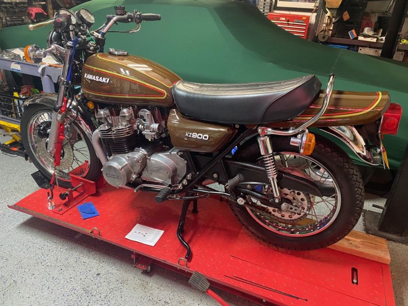 WheelHop's KZ900 BOTM for April '24
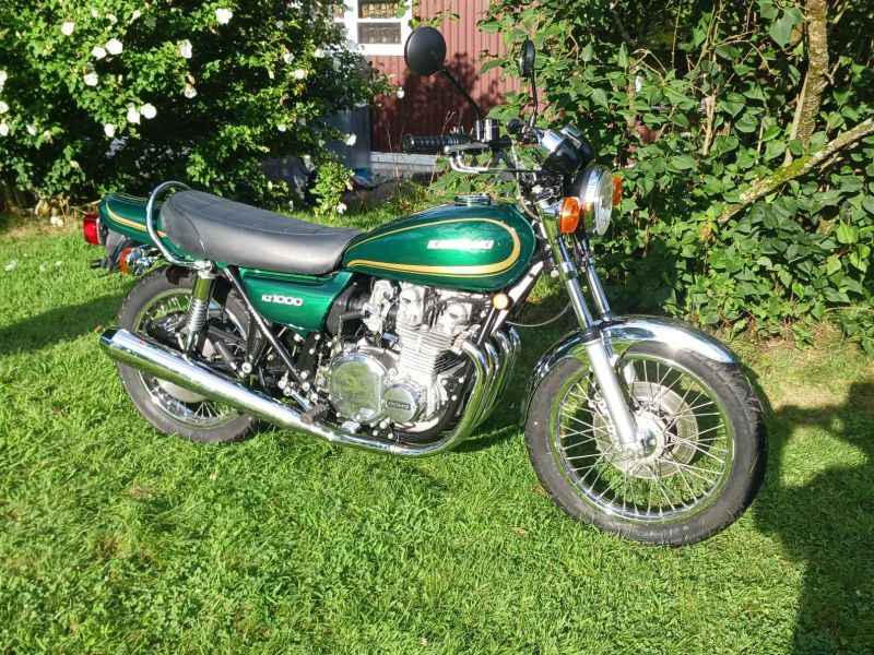 Ronnie V's BOTM for December 2024
