We recently completed the content of this post to be published in the VJMC NA magazine as a Tech article. It is in the hands of the Editor of the magazine now.
Most of the VJMC membership would not be as familiar with the particulars of setting fuel level on Z1 carbs as are the members of this forum. In that respect, most of our forum members are likely to find some of the following post dumbed down with what is redundant & common knowledge among ourselves. It was easier to post the piece in it's entirety than to do painstaking edits throughout to keep from boring y'all. What we hope to be of particular interest are the experiments with the clear glass cup as substitute for a float bowl and clear tube combo. Likewise, our experiments with other liquids may be informative.
This probably won't be the last contribution from us on this subject. These are experiments, and further development is likely.
slmjim & Z1BEBE
Legal disclaimer-type stuff -
This thread involves working with gasoline and other liquids that are poisonous, flammable and produce explosive vapors. Wear eye protection, chemical resistant gloves and clothing when working with the volatile liquids described in this article. Work with these liquids outdoors with adequate ventilation. Do not smoke or allow any open flame, spark or other source of ignition when in close proximity to these volatile liquids. Keep children and pets away. Keep the work area away from structures. No one is responsible for your actions and consequences thereof other than yourself.
Float adjustment on many motorcycle carburetors is done by physically measuring the distance from a common reference point, such as the float bowl gasket surface of the carb body, to the bottom of the float bulb(s) with the carb body in a particular orientation. This sets what we'll call the
physical float level. Another method of float adjustment is often referred to as the clear tube, or wet method. The wet method sets actual
fuel level,
not the
physical float level. Setting physical float level can result in fuel level being incorrect in some instances if the float is misshapen or otherwise not perfect.
In this article we're going to explore a variation of the clear tube, or wet method of setting carburetor floats. We, the authors, cannot lay claim to this alternate wet method. slmjim saw it described long ago, either in print or online. We merely present it here in hopes our experiments might benefit other DIY Riders.
The wet method has historically involved attaching a clear tube tool to a carburetor float bowl drain in such a way that the
actual fuel level in the float bowl can be observed externally. The wet method is specified in the OEM Kawasaki White Manual for Z1's. We focus exclusively on Z1's for our vintage bike affliction, so we will use Z1 carbs as examples.
Kawasaki offered two, very different, clear tube special tools for the Mikuni VM28SC carburetors on Z1's, because two variations of the VM28SC's were installed during the 3 year production run of Z1's, with each variation utilizing very different float bowls. Those OEM tools have been difficult to find for a long time, and are expensive if located. When using the Kawasaki factory fuel level clear tube tool, if the float needed adjustment, the float bowl screws would have to be removed along with the float bowl, then the float pivot pin removed, freeing the float itself. The float tang could then be adjusted (
formed* ) slightly, the float reinstalled, the float bowl and screws reinstalled then test again with the clear tube tool. If the float level was still wrong, the float bowl screws, float bowl, pivot pin and float would need to be removed once again, tang adjusted, float/bowl/screws reinstalled and fuel level observed again in the clear tube. Tang adjustments are
very tiny. Moving the tang just a few thousandths will produce a relatively large change in fuel level. It's sort of a learned art.
Repeat as needed.
For four carbs.
Tedious? Indeed...
What if there was a faster, easier, more universal way to check wet fuel levels without needing to use a special tool? What if such a method could be used on many motorcycle carburetors where in the wet fuel level is known?
Before we get into the particulars, we must first revisit our high school chemistry class 101. The term we are looking at is
meniscus.
A
meniscus is a curve in the surface of a molecular substance (in our case liquid fuel) when it touches another material. With water as a common example as well as fuel, you can think of it as when water sticks to the inside of a glass. A concave meniscus occurs when the molecules of the liquid are more strongly attracted to the container (adhesion) than to each other (cohesion), causing the liquid to climb the walls of the container.
Fuel forms a concave meniscus. See illustration.
For our purposes, we are only interested in the example of a concave meniscus on the left, labeled as ' A '.
' A ' is an example of a concave meniscus in a small vertical tube, wherein the true level of the fluid is at the
bottom of the curve at the dashed line; the liquid meniscus that has climbed up the sides of the tube due to surface tension is to be ignored. In a large enough vessel, the meniscus will only be present where the fluid is in contact with the walls of the containing vessel. The remainder of the liquid surface starting at a very short distance (1mm ~ 2mm) from the inner wall of the vessel will essentially be flat. Later in this article we'll be referring to this large, flat liquid surface as the
flat fuel level.
When observing fuel level in a clear tube tool, care must be taken to read the fuel level at the
bottom of the concave meniscus. That can be difficult depending on lighting and viewing angle. Fuel dye could help. Too, if the inner diameter of the tube is too small, surface tension can cause the meniscus to creep up the wall of the tube far above the actual fuel level, thereby creating an equally large error in the perceived fuel level.
Our test setup consists of an external fuel tank, a fuel ' T ' with one outlet blocked, and a level surface on which to mount a carburetor and/or flat, level surface for a glass cup (test vessel) to observe fuel level. Here it is shown with a single carb clamped for easier use of a clear tube tool. Table is an old, first gen. Black & Decker WorkMate portable work table. Vintage coat rack/aux. fuel tank hanger courtesy Goodwill.:
The two halves of the WorkMate act as a vise, and can be easily separated and adjusted to clamp a single carburetor gently, level and securely as seen here. The table can also hold a board to use as a flat work surface for the glass cup test vessel described later. We also place shims under two legs to account for pitch of the patio floor. While carbs often are not bubble-level when mounted to a bike engine, we feel good leveling is necessary for reproduceability.
Now on to the experimental wet method that is the main subject of this article.
Here we see the WorkMate with the flat work surface board clamped in place, along with the glass test vessel (glass cup). For you eagle eyes, make no mistake; the Miracle-Gro box top is a Über-precise shim for precision leveling

. More on the glass cup shortly:
Carb with fuel ' T ', one outlet capped. Teflon plumbing wrap enables an old, time-and-ethanol-shrunken ' T ' to be used without leaks.:
Our first set of tests are to establish a baseline. Slmjim ( Z1BEBE..., not so much ) has been curious for years as to whether there is a difference in fuel level between pure gasoline and E10 (10% ethanol) fuel. These baseline tests are done using the old Kawasaki OEM clear tube adapter that screws into the 17mm drain plug / main jet cover at the bottom of the float bowl that was only used on Z1 and early Z1-A carburetors. Late Z1-A and all Z1-B carbs used an entirely different float bowl and clear tube tool. A Z1-B-style clear tube tool can be easily and inexpensively mimicked as described at the end of this article for use on many other carbs.
The OEM tool is seen here empty prior to turning on the tap but held in viewing position. The two small hose clamps seen at the bottom of the clear tubing are simply there to keep the tubing from kinking at the bend; they serve no other purpose.:
Here we see fuel level using pure gasoline. The level appears to be ~3mm below the edge of the carb body, which meets calculated spec. Note that it's a little difficult to discern where the meniscus ends at the bottom of the concave.:
And here we see the same carb with E10 fuel. Concave bottom slightly more defined. Function of the ethanol content..?:
Considering the 0.5mm error in the position of the mm scale re: the edge of the carb body between the two pics, the fuel level of E10 appears to be ~1mm lower than that of pure gasoline. That helps reinforce the observation of slightly lean running behavior observed on the bike these carbs came from. The lower the fuel level, the leaner the mix. While 1mm doesn't sound like much, we'll see shortly that there is very little wiggle room in the spec of Z1 carb fuel level.
So, there apparently is a small but perceptible difference of fuel level, pure gasoline vs. E10 fuel. Which is correct? Well..., both. Because E10 fuel is so ubiquitous in our region, we used E10 fuel for the remainder of this experiment.
In the OEM Kawasaki White Manual for Z1's there is a specification in Table 3 for
fuel level of the Mikuni VM28SC carburetors. It is given in a table as 32 millimeters +/- 1 mm or, 1.26 inch +/- 0.040 (40 thousandths):
That specification confounded us for years until it was finally realized the spec was describing the fuel level as
the distance below the centerline of the venturi bore to the flat fuel level in the float bowl. See White Manual illustration #273 below. The added arrows and text for HORIZONTAL BORE CENTERLINE, FUEL LEVEL IN CLEAR TUBE, and 32MM ( flat fuel level position below centerline ) are ours for clarification:
Notice that when measuring 32mm below the venturi bore, it falls somewhat
above (not to scale) the level indicated in the illustration of fuel level in the clear tube, which shows fuel level being
at the shoulder of the float bowl. The shoulder of the float bowl is slightly beyond the lower level of the range specified in Table 3. Many (including us) have been frustrated by performance problems when setting fuel level to the edge of that shoulder as illustrated due to lean running on the needle jet.
Elsewhere in the White Manual, Mama Kaw specifies a fuel level of “ '
about' 1/8 inch, or 2.5mm ~ 4.5mm below the edge of the carb body”. That seemingly tiny range can result in surprisingly wide variations of richer-to-leaner running while on the needle jet and at the transition from pilot jet to needle jet at small throttle openings. In our experience the lean behavior is most pronounced on the late '74 Z1-A and all '75 Z1-B carbs with the 1.5 slide cutaway and other factory jetting changes.
Being a Technician by temperament, slmjim really doesn't like vague 'about' descriptions where some precision is not only preferable, but readily available in the specs. Once it was realized what was meant by the vaguely referenced 32 mm (flat) fuel level, we could ignore the vague 'about' description and pursue a
precise flat fuel level adjustment.
Now we get to the real meat of the clear tube/wet variation. What we are testing is the concept of removing
only the float bowl of the carb to be adjusted, and placing the carburetor
with float installed into a shallow vessel (referred to henceforth as 'glass cup') suitably wide enough to not interfere with float movement, narrow enough to securely support the carburetor body in a level position at all four corners, and shallow enough to not require a large volume of fuel.
The glass cup used in this project was found in our kitchen cabinet when we moved in 27 yrs. ago. The Lovely Z1BEBE mentioned that it might be antique. All the better, because we're working with vintage technology anyway. Still, what are the chances the universe knew that, one day there would be VM28SC's, and slmjim one day looking for some random clear vessel specifically for them... coincidence? Another conversation for another time & a few beers.
Carefully measuring 32mm below the center line of the venturi bore places the intended fuel level at 3 mm below the edge of the carburetor body. With that specification in hand we used a glass cutter to scribe a line all the way around the glass cup precisely 3mm below the lip. That becomes the target
flat fuel level in the glass cup when the float is correctly adjusted. Scribed line seen at red arrows.:
Completely set up, using the same carburetor with which we determined the baseline variations of fuel level re: pure gasoline vs. E10 and, filled with E10 until stopped by the float, the experimental arrangement looks like this:
The meniscus that develops all the way around the inside of the glass cup can be easily ignored by focusing on the flat fuel level in the cup, which discounts the meniscus altogether. The flat fuel level can be seen much more easily in person than in the pic above. We can easily see that the flat fuel level in the glass cup is lower than the 3mm scribe line. A closeup helps. Red arrows at scribe line, yellow arrows at flat fuel level:
Now it's just a matter of removing the carburetor from the glass cup, placing it on a larger work surface, removing the float pivot pin, adjusting the float tang, and reinstalling only the float. Empty an ounce or so of fuel out of the glass cup, place the carburetor on the glass cup once more, turn on the fuel and wait for the fuel level to stabilize. No screws, float bowl or clear tube tool to deal with.
Because of some distortion resulting from diffraction of light passing through the fuel, and some distortion caused by the curvature of the glass cup, being able to precisely determine the flat fuel level in the glass cup can get a little tricky if the meniscus falls directly on the scribed line. We were able to make the flat fuel level much more visible by gently tapping the work surface, especially if the meniscus fell directly on the scribed line. The resulting movement and ripples of the fuel in the glass cup made it easy to see where the flat fuel level was, while making it much easier to ignore the meniscus. We also quickly realized that we had to pay careful attention to eye level when viewing the flat fuel level, so that we were viewing it on the same plane to prevent parallax error.
Once the float level was set we simply repeated it for the other three carburetors. A project that would usually require at least 2 tedious hours of removing and replacing float bowls for each adjustment on four carbs became much more rapid.
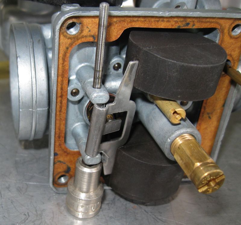
An aside that may not be specific to Mikuni VM28SC's - The float pivot pin is more of an interference fit in the float pivot pegs of some carburetor bodies than others. In the past, we have seen a few forum entries, and a few ruined carb bodies at swap meets, where unfortunae do-it-yourselfers have broken a float pivot peg off of a carburetor body by using too much force while attempting to remove or install the float pivot pin from an unsupported float pivot peg. Our solution is a random quarter inch drive socket from a mismatched set that we use as a support for the float pivot peg when removing and installing float pivot pins. It just happened to be exactly the correct height:
While we had the experiment set up, we (slmjim rather) decided to explore alternate liquids for testing fuel level and float adjustment, something we've (he's) been wanting to do for years. We often work on carburetors during the winter and have wanted to be able to set floats safely in the basement workshop. It's not only about fumes creating odor in the house; it is the safety aspect of a standing pilot light in the water heater being so close to the service bay and carburetor bench as a possible ignition source.
Our first test was with ordinary tap water. Water being much more dense than gasoline, it is clear that the resulting liquid level is far too low to be useful for float adjustment. Water level seen at yellow lines:
Our next test was with 70% isopropyl alcohol. It was closer than water but... :
After that we tested WD-40 from a bulk gallon container. It was much closer than either water or 70% isopropyl alcohol but still about 1 mm low:
Next test was with kerosene:
Still too low, and is flammable to boot.
We will continue our search for a safe alternative for testing fuel level in a basement workshop.
Our experience is that floats are usually set-it-and-forget-it for a long time. They just don't seem to drift. Z1 carbs aren't that hard to split from the rack anyway. That's why we do float adjustments with carbs off the rack. The glass cup process can be adapted to racked carbs, but we haven't done it. We've seen pics where others have done so using mounting jigs to hold the entire rack.
So here's what we learned:
1) A faint, whitish scribed line in glass is difficult to see in many lighting conditions when attempting to view the flat fuel level immediately behind it. We need to develop a much more more visible, fuel-proof and very thin marking with which to determine flat fuel level. A clear cup with precise factory millimeter graduation marks would be perfect, but we don't know of any such vessel of appropriate size. A search is in progress.
2) Three millimeters gives
very little room for error if the float sticks, is adjusted too high, or if a float needle happens to not seat and leaks. It can get messy, and one needs to be quick on the shut off valve from the auxiliary fuel tank.
3) It's a messy process anyway in ideal circumstances. It's best done outside until a fuel substitute is found.
4) A user needs to be careful to place their eyes in the same plane as the flat fuel level to avoid parallax errors from creeping in.
5) Water, 70% isopropyl alcohol, WD-40 and kerosene not good substitutes for fuel level testing. WD-40 is much closer to gasoline, and kerosene slightly closer yet, but neither are identical to E10 fuel. We will continue our search for a suitably safe, non-flammable liquid substitute for use in an enclosed shop.
6) A Miracl-Gro box top makes a really handy precision adjustment shim for leveling a work surface.
We mentioned earlier how to simply mimic a tool like that used on late Z1-A and all Z1-B carbs that have a small drain screw instead of the large 17mm main jet cover/plug used on early Z1 carbs. That OEM Z1-B tool replaces the small drain screw at the bottom of the float bowl with a hollow screw and hollow ' T ' that has the clear tube attached to it. An easy & cheap alternative is to use any flexible, clear plastic tubing of appropriate length and outside diameter. Simply 'screw' one end of the tubing into the float bowl drain hole until it's firmly held. If necessary, trim the end to a blunt conical shape to ease entry. A dab of of slickum can help ease with twisting into the screw hole threads.
* A good Tech never
bends anything. It is
formed.
Hope y'all enjoyed. These experiments are the product of amateur hobbyists and less-than-ideal photography. There may also be disagreement with some of our technical observations and opinions. If anyone experiments with the glass cup method, has any suggestions for improvement or constructive criticism, please share. We'd (slmjim mostly) be happy to test suggested variations as time allows, This thread is intended for everyone.
Good Ridin'
slmjim & Z1BEBE


") I'm no mechanic but I do like to learn how things work and problem solve so about 4 years ago judging by the state of my spark plugs I thought I'd try adjusting the float levels, first time for everything
I'm no mechanic but I do like to learn how things work and problem solve so about 4 years ago judging by the state of my spark plugs I thought I'd try adjusting the float levels, first time for everything  I figured the best chance I had was to measure the float levels using steel rules, calipers and a sheet of perspex I made up and then use the tube system but I didn't want to spend £20 on a tube tool and do one at a time so I simply drilled and tapped four bolts and made four tubes, it was still a pain adjusting, assembling, filling with fuel and measuring ,I think it took five adjustments as in five times disassembly and reassembly but I got there and the bike has run amazing and strong ever since, I also balanced the carbs as soon as they were back on, even now the spark plugs are a nice off white and a teeny bit sooty and all the same as each other so I'm glad I did the job and maybe learnt something too
