Welcome, Guest
Username: Password: Remember me
  • Page:
  • 1
  • 2

TOPIC:

1984 KZ550F Shaft EFI Conversion 03 Aug 2020 22:39 #832189

  • kz_chris
  • kz_chris's Avatar Topic Author
  • Offline
  • User
  • Posts: 17
  • Thank you received: 4
Quick update: I've been working every day on the conversion, and am about to print the final TB adapters by the end of the week. After that I'll post the video depicting the entire design and prototyping process on that part. In the meantime I've been designing and prototyping 36-2 and 24-2 crank triggers and IAT sensor mounts using existing features on the throttle bodies. I'm going to pull a favor and hopefully get the 36-2 and 24-2 sprockets waterjet sometime later this week. The machine has a 0.005" to 0.01" accuracy so we're hoping the press fit design will work. Otherwise I'll either use a friend's drill press to open the hole up bigger, or tack weld the sprocket onto the pulsing coil piece.

I'm almost finished converting my (free) computer power supply into a benchtop power supply. It'll have 3.3V, 5V, and 12V rails with a max 12V amperage of 18A (almost the same as my bike). I plan to bench test the electronics independently before throwing them on the bike. Last week all of my EFI components from DIYautotune arrived. I'm ordering a few connectors and other items soon, and will hopefully be starting some assembly on the bike within the next 3 weeks. After the components I mentioned are printed and designed, I'll still need to design the fuel return adapter which will sit where the fuel level sensor usually sits. My bike didn't have one when I bought it, so I'm not losing any functionality there. I'll also need to design a jig to orient the trigger wheel for press fit, which should be pretty quick.

Here's a picture representing some of the items I've prototyped so far. Others are currently on the bike/TB's. I've logged around 180 hours of 3D printer uptime in the past two weeks prototyping and tuning the machine to produce functional parts.


More in depth update will be posted both here and YouTube by Sunday.
1984 KZ550F
2007 SV650N
Attachments:

Please Log in or Create an account to join the conversation.

1984 KZ550F Shaft EFI Conversion 04 Aug 2020 07:23 #832210

  • kzstreetfighter71
  • kzstreetfighter71's Avatar
  • Offline
  • User
  • Atlantic West Coast
  • Posts: 876
  • Thank you received: 250
wow... next level stuff going on here!
06 Gsf 1200 bandit, 08 Triumph tiger 1010
05 Yam xv1700 , 02 Hon shadow 1100
1975 Z1 (currently working on)
1977 Z1000 ( running and in storage)
1978 Z1000 (currently working on)
1978 Z1r "skinny tank" (currently working on)
1978 Z1r "fat tank (gathering parts)
1979 z1000st (currently working on)

Please Log in or Create an account to join the conversation.

1984 KZ550F Shaft EFI Conversion 19 Aug 2020 23:33 #833289

  • kz_chris
  • kz_chris's Avatar Topic Author
  • Offline
  • User
  • Posts: 17
  • Thank you received: 4
Hey all,

I finally have a big chunk of time free (final exams and some other stuff came up) and am here to bring the forum up to speed on my project. I've kept up working on this project every day and documenting my progress, but have procrastinated on compiling and posting it all .... until now!

In this post I'll cover the throttle body adapter design. For this, I chose to iteratively design components and focus on refining a few aspects at time and prototyping until I had something I liked.

Before designing my actual adapters, I felt it important to gauge my 3D printer's tolerances and manufacturing capabilities. For this, I printed several rings of different ID's to see which felt best to put on and take off of the throttle body. The proper throttle body OD here is 53mm and I tested from 53.05mm to 53.25mm in 0.05mm increments. I initially liked the fit of the 53.15mm diameter and used it for V1 of the TB adapters, but later changed it. Below are some pictures of the test rings I printed. Keep in mind, 1mm is 0.040" and those increments are grasping at my printer's max resolution.


Now that I had a target ID for the TB adapter lip, I started designing. V1 was a simple design where I was checking TB fitment overall, and also checked engine fitment. This version bolted up to the engine perfectly. I chose a 4mm thickness arbitrarily for the flange, compared to the 6mm on original carb boot. Here's a pic of V1.


When designing V2 I accounted for the eccentricity of the TB outlet, pictured below. I measured the eccentricity as 3mm above the center of the outlet. In modeling this, I realized that the easiest way to implement this design would be to restart the sketch hierarchy from scratch, and subsequently moved on to V3. V2 was a transient model that was never made, just saved some dimensions.

For V3, I designed the adapter with the eccentricity, added a retaining lip for the TB, bumped ID to 53.25mm, and added fillets connecting the vertical section to the bottom flange. In this version I also changed my model to have the exact same footprint as the previous carb boots. While designing V3, I totally forgot to make the opening for the TB bigger, which is why it looks different than the other versions. Oops, It'll get fixed in the next iteration.


Whoo! TB fit onto the adapters and held with the inbuilt ring, while the adapter is fastened to the engine! That's a win. Time to move on to V4.


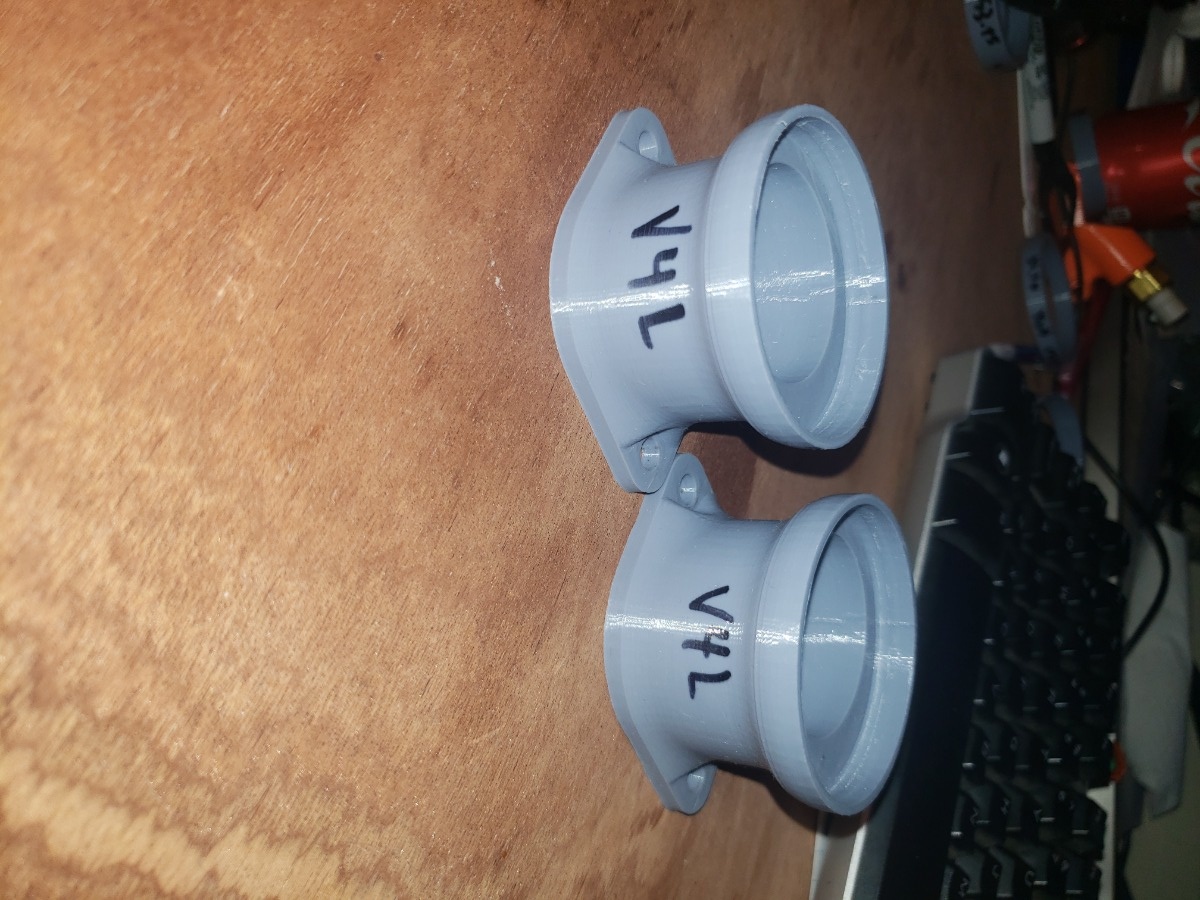
For V4, I re-added the eccentric opening for the TB, made the adapter taller to better accomadate the fasteners and allen keys to reach them, and then made generic Left and Right versions of each TB adapters, because the eccentricity of the throttle body and perpendicular bolt pattern between engine sides means that they'd need to be different. V4 was a success! Now to account for the different cylinder spacing vs TB spacing within adapters.


V5 took some work, and was the point where 4 seperate models were created. To properly space the adapters, I'd need 4 models anyways (Generic Left, Generic Right, and +2mm space Left/Right for each side). Since I'd need 4 models anyways, I decided to center the spacings and have each model be +/- 1mm in the appropriate direction. I also added some numbering on each to identify each adapter easily. At this point I finally bolted on one throttle body rack to the engine! I whipped up some engine spacers and finally bolted the entire throttle body rack on!


V6 was pretty much the same as previous versions, except the engine geometry was fixed so that the Tb outlet fit perfectly to the engine block. I had originally relied on my eye-crometers as judging the flange fasteners at a 45 degree angle and then realized that the proper angle was 60 degrees after measuring again. Here's V6 next to the original boot.


Engine flange - right side


All 4 V6 adapters holding the TB, which was properly spaced out 17mm.


I'll start a second part now to fit more pictures and continue the discussion.
1984 KZ550F
2007 SV650N

Please Log in or Create an account to join the conversation.

1984 KZ550F Shaft EFI Conversion 19 Aug 2020 23:36 #833290

  • kz_chris
  • kz_chris's Avatar Topic Author
  • Offline
  • User
  • Posts: 17
  • Thank you received: 4
I just realized most of those images uploaded sideways. Anyone have a way to fix that? They show up in correct orientation on my computer and in the files preview I believe. I'll be more cognizant for part 2 of the TB discussion.
1984 KZ550F
2007 SV650N

Please Log in or Create an account to join the conversation.

1984 KZ550F Shaft EFI Conversion 20 Aug 2020 00:13 #833292

  • kz_chris
  • kz_chris's Avatar Topic Author
  • Offline
  • User
  • Posts: 17
  • Thank you received: 4
Part 2 of TB adapter design discussion:

I'll start off by showing a pic of some failures along the way. Here lies a batch of V5 adapters which fell victim to a power outage and never finished. Since then, I've added power outage print resume capabilities to the printer!


Next are pics of V1, V3, and V4L next to one another


Here's the entire line of prototyped adapters


A picture of V5 directly


A picture of V6


The design has been prototyped and is ready for the final version. I printed all prototypes in PLA plastic, a low cost, easily printable filament. The final adapters are going to be Taulman 645 Nylon filament, which has the properties of Nylon 6-6 (fuel and oil resistant). Printing Nylon is no joke, and I took well over a week of my time modifying my printer and entire setup to accommodate it! Nylon is extremely hygoroscopic and must be printed without moisture, or else the print will have bubbles and will have poor layer adhesion. I modified a food dehydrator to hold the filament spool and placed lines routing the filament directly to the printer head. Doing that, and replacing my 3D printer bed, hot end, firmware, adding an extra stepper motor, and tramming the Z we're ready to print!

I first printed the cylinder 1 V6 adapter in Nylon at a reasonable layer height at 20% infill (how much plastic fills the interior of the part). As a test print it came out pretty well, but the filament definitely wasn't dry enough. I dried the filament more and printed cylinder 2 V6 adapter using the same settings aside from 40% infill. Nylon is pretty ductile and I wanted to experiment with the best infill percentage around the lip to allow the TB to fit perfectly.

Here's a picture of the two nylon prints side by side.


Before printing my absolute final nylon pieces, it's important to test and determine the best settings for a strong print. My adapters will at max hold a few pounds each statically and see ~10lbs of axial force when you remove the TB rack, but the layer adhesion will be a determining factor on having a sturdy piece. To narrow down these print settings, I printed a couple of carabiners at different nozzle temperatures and used a fishscale to pull them down. I found that printing at 260C gave best results. A picture of the broken temp test carabiners is below.


They both broke at the same location and same way. 250C had a breaking strength of 17lbs whereas 260c had a breaking strength of 23lbs. To establish a proper pattern, I'd print more - but Nylon is expensive and takes super long to print. I watched videos of people who'd done similar tests and they seem to have had the same consensus.

The next thing I tested was the layer height of the print, which greatly affects surface finish and feature accuracy. I tested 0.08mm, 0.12mm, 0.2mm, 0.28mm, and 0.32mm. Here are the results :


Making an excel sheet accounting for part density and breaking strength, I made a bar chart relating the max stress each part can handle. As expected, the smaller the layer height the stronger the part (for Nylon's case).


Printing at 0.08mm layer height and 260C is strongest, but printing at such fine detail would make each adapter print for almost 12 hours! I'll have to decide which layer height is the best compromise.

I have some more photos to upload, so I'll cut this reply now and shorter part 3 (hopefully).
1984 KZ550F
2007 SV650N

Please Log in or Create an account to join the conversation.

1984 KZ550F Shaft EFI Conversion 20 Aug 2020 00:32 #833293

  • kz_chris
  • kz_chris's Avatar Topic Author
  • Offline
  • User
  • Posts: 17
  • Thank you received: 4
Part 3!

Here I'll show some proper CAD screenshots of all 6 versions side by side to give some visualization to the iterations. V1 is on left and V6 is on the right.


Front View


Side View (Left)


Top View


The throttle body adapters have been designed, prototyped, and iterated. Final printing is yet to come. How will I keep the 3D printed parts from melting?

I'm planning on using a sheet of Buna N Nitrile Rubber as a heat break between the intake flanges and the TB adapters. This is the same material that the stock carb boots are made of, and is fuel/oil resistant and has a working range up to 170F-220F depending on manufacturer. On McMaster-Carr, I've found some high temp nitrile rubber that has a working range up to 300F. I'm planning on buying a sheet and using an exacto knife to cut them at first. Once I have the bike more ironed out I'll pull a favor and get a friend to waterjet them.

Choosing the thickness is it's own dilemma. As an engineering student hoping to use this project in my post-grad job search, I want to justify each and every decision for this conversion as quantitatively as possible. I took a heat transfer class last semester which gave me a toolset of equations and methods to solve problems dealing with heat flow through anything. After revisiting my lectures, notes, textbook, and old Hw's I realized that in each problem the material thickness was already given and then used to solve for intangible characteristic values! After realizing I hadn't quite seen a similar problem (which would seem deceptively easy at first), I reached out to my old professor to ask for guidance on the problem. We'll see what he replies!

If you've read this far I'd like to thank you! I was pretty long-winded for just an adapter explanation, but I wanted to fully hash out my thought process and show the amount of time and effort I'm putting into this conversion!

I've been typing these replies for several hours and still have atleast 2x as much left to write about the other aspects I've worked on since the last major update. New content has been filmed but I haven't gotten around to editing it for the YouTube channel.

I'll pick up and write discussion posts on fuel pump testing, connector identification and purchasing, trigger wheel design and prototyping, fuel rail extension, sensor mounting, and more soon.
1984 KZ550F
2007 SV650N
Attachments:

Please Log in or Create an account to join the conversation.

1984 KZ550F Shaft EFI Conversion 14 Sep 2020 11:07 #834994

  • kz_chris
  • kz_chris's Avatar Topic Author
  • Offline
  • User
  • Posts: 17
  • Thank you received: 4
It's been a few weeks, so I thought I'd give an update on the project status. My initial goal was to have the bike start-up by September, but unfortunately with some budget and planning issues, I didn't quite meet that deadline. The majority of this time has been trying to find a place where I could waterjet my crank trigger wheels without paying an arm and a leg. One place gave me a quote of $1000 for 4x2" diameter sprockets! I'm just assuming they didn't want to run my parts.

I waited and tried to find the best solution. I ended up pulling a favor and getting them Plasma cut for free. Finding someone to do it and manufacturing time has taken the better part of the past two weeks. On the bright side, I'll have those parts by the end of the week and have a usable crank signal.

My brother bought and assembled a jim stim and I've played around with the tuner studio software for a good bit. My wiring harness is almost fully complete aside from a few of the butt connectors I still need to crimp. Part of the difficulty with my bike specifically is that I realized the ignition system has been completely swapped with that of an 85+ ZX550 from what I could tell. To accomplish the best ignition tuning, I ended up buying a Bosch igniter to directly control the coils from the microsquirt. I had initially planned to swap wires leading to the ecm, but the built in advance would've been troublesome. I bought the 8ft harness with my Microsquirt and have kept everything full length. Once I get the bike running and working correctly, the plan is to shorten the leads to a proper length and package everything within the bike.

I'm running a fuel pump/injector wiring test today to verify that they work correctly. I also had a fuel rail extension designed and manufactured, which I'll test as well. Other than that, the bike is in pretty good shape! I got my wideband bung installed on the exhaust header such as not to interfere with my center stand, and have all sensors calibrated within tunerstudio. I've got to look into my ignition settings and initial fuel map more, but am in a good position right now.

I've been documenting all steps of the process and will write a more in depth forum post soon and then upload some of my footage to new YouTube videos. I'm in my last semester of college now so I'm juggling 15 credits along with job-hunting and this project!
1984 KZ550F
2007 SV650N

Please Log in or Create an account to join the conversation.

1984 KZ550F Shaft EFI Conversion 14 Sep 2020 12:41 #835006

  • loudhvx
  • loudhvx's Avatar
  • Offline
  • KZr Legend
  • Posts: 10868
  • Thank you received: 1615
Nice job with the TB holders.
The kawasaki fiche for the 84 Kz550F2 shows the ignition with the electronic-advance, so maybe it's stock. The same fiche also shows the older ignition, but that may be for the 1983 Kz550F1.
The following user(s) said Thank You: kz_chris

Please Log in or Create an account to join the conversation.

1984 KZ550F Shaft EFI Conversion 12 Oct 2020 13:37 #836718

  • kz_chris
  • kz_chris's Avatar Topic Author
  • Offline
  • User
  • Posts: 17
  • Thank you received: 4
Thanks for the heads up, Loudhvx! I haven't progressed on the bike build for a few weeks now, but am finally finding some time to continue my work now that I have my crank trigger wheels.

I'm finishing up my wiring for first start and am having issues identifying my ignition system. My F2/M1 shaft service manual has a completely different ignition system and wiring colors so I'm at a loss.

To reverse engineer the wiring I used ZX550/Zx400 Ignition wiring info that loudhvx had posted a few years ago. I think that my rotor pulsing coil could be from a GPZ550, but would appreciate any help identifying it.

I measured the angle between T-F as 13.6-ish degrees and the distance between T and the third tick as 40 degrees on the dot. Pics below of the pulsing coil, VR sensors, and igniter. The igniter specifically isn't as described in my manual and was located near the neck of the frame as opposed to the below-battery position noted in the manual.

Two VR Sensors and Pulsing Coil


Igniter/CDI box


10-pin connector (9 Used)


Ignition Coil (cyl 1 & 4)


Ignition Coil by itself
1984 KZ550F
2007 SV650N

Please Log in or Create an account to join the conversation.

Last edit: by kz_chris. Reason: Fixed image orientation

1984 KZ550F Shaft EFI Conversion 12 Oct 2020 16:52 #836732

  • loudhvx
  • loudhvx's Avatar
  • Offline
  • KZr Legend
  • Posts: 10868
  • Thank you received: 1615
I updated the Zx550 igniter notes with part numbers including those for the Kz550F2.

I think the parts may indeed be from a Zx based on the igniter part number 21119-1113.
The Kz550F2 should have come with 21119-1029 igniter.
Most Kz550F2 models used the same rotor as the Zx, which is what you have (1104).
The California model Kz550F2 uses 1120.

Presumably, a different rotor or different igniter will affect timing (and possibly dwell, though unlikely).

Attachments:

Please Log in or Create an account to join the conversation.

Last edit: by loudhvx.

1984 KZ550F Shaft EFI Conversion 13 Nov 2020 07:51 #838424

  • Saablord
  • Saablord's Avatar
  • Offline
  • User
  • Posts: 222
  • Thank you received: 59
how in the heck did i miss this thread?!

Sweet build you have here; im working on a EFI turbo conversion. Check out my thread kzrider.com/forum/forum-index/11-project...-810-turbo-e85-build

I've made my own crank trigger which might give you some ideas. I would recommend ditching the stock coils and ignition box and going to COP, or use the stock ignition and only modify fueling with the ECU. Or just control the kz coils with some external drivers (basically, dont use the stock ignitor)

I am very worried about your 3d printed adapters though... i went down that route before and it never worked. the melting point is 260, but it deforms much sooner than that. I never tried using rubber as an insulator, but you're going to need a thicker bolt flange.

how are you sealing on the TB side? looks like you have a the retaining feature in the 3dprinted part that matches the TB, but that wouldn't seal nor really hold the TB in place... what am i missing?

If you need custom boots they should be aluminum or 3d print some molds and case urethane around a steel plate like the stock boots.

Please Log in or Create an account to join the conversation.

Last edit: by Saablord.
  • Page:
  • 1
  • 2
Powered by Kunena Forum