
HEI Conversion question
- loudhvx
-

- Offline
- KZr Legend
-

Registered
- Posts: 10863
- Thanks: 1622
Re: HEI Conversion question
10 Jun 2015 10:13
Thanks for the update.
I have been doing some more testing as well, and you are right. The BWD modules are very close to working properly, however, not 100%. The effect of using higher-ohm coils, like anything higher than 2 ohms or so (I'm still trying to nail down the number), is that the module tries to produce multiple sparks in one revolution. It tries, and usually fails, so it's not necessarily unsafe, but might make for very difficult timing using a strobe light.
When I use it with a low resistance (like from a car) coil, it works reliably, and as expected, but is not ideal. The KZ pickup signal is trying to give longer dwell, and the coil doesn't want it, so the module goes heavily into current-limit mode. This creates a lot of heat in the coil and the module gets real hot. Not good. But, this does give me more reason to develop a system that uses cheap car coils (how nice would it be to use $30 car coils instead of $80 bike coils). I just have to find a way to reduce the kz pickup signal's dwell. It's not difficult, but I had no real impetus to develop it. the real problem, for me, is that there are no small/cheap car coils that fit the 550 frame.
My fav would be the Dodge Neon coil pack. It looks tailor made for inline fours, and is dirt cheap on ebay. I've tested and abused the SH** out of the one I have, and it just shrugs it off like nothing. But it's just a little too big to fit under the tank.
1981 KZ550 D1 gpz.
Kz550 valve train warning.
Other links.
Kz550 valve train warning.
Other links.
Please Log in or Create an account to join the conversation.
- rrsmsw9999
-

- Offline
- User
-

Registered
- Posts: 775
- Thanks: 65
Re: HEI Conversion question
11 Jun 2015 22:03
Here's what's coming in the box Jim, I will ship it out tomorrow.
R
R
Attachment IMG_1331.jpg not found
1980 KZ 1000E2
Crashed 6/2016
1980 KZ550A
Sold 3/2016
Crashed 6/2016
1980 KZ550A
Sold 3/2016
Please Log in or Create an account to join the conversation.
- Nautilus88
-

- Offline
- User
-
Registered
- Posts: 5
- Thanks: 4
Re: HEI Conversion question
11 Oct 2018 22:41
Hey Lou! First thing I want to say, is thank you so much for all the work you put in over the years to help us UJM guys out. When I first saw your diagram, I was thrilled that someone took the time and effort to design and post something like that. But after hours of scouring the net and stumbling upon this thread, I have to say, I'm blown away by just how helpful you have been and how much effort you put in to help out. I build and repair guitars, and get tons of questions that sometimes take a lot of testing to find solid answers to, so I understand just how exhausting and time consuming it can be. But it seems, like me, you truly want to help and find it worth your time to do so. And that is greatly appreciated. Your work has had to have helped so many people over the years. So again, thank you!
The reason I'm digging up this old thread is to ask if you've ever come to any conclusions about the newer modules. I just finished building my '80 KZ750 ltd and after running through every possible procedure to rectify a cyl 1&4 cold-fire, I realized that my igniter was bad, and ouch! The prices are absurd, but I knew there had to be a work-around. I found your info earlier today and grabbed a couple modules and had the components in stock in my shop. But Autozone only had one DR100, so I grabbed a CBE4 from Advance. I got the whole system wired up, but after stumbling upon this, I'm wondering if I made a mistake by grabbing the CBE4 in my haste to get this done tonight. I'll attach a pic showing the system wired up and the box for the BWD module. It doesn't specify CBE4P, just CBE4, so I'm wondering if I'll be able to make do with this, and if not, is there anything else I need to be aware of that's come to your attention since your last response here? I would greatly appreciate any info you're willing to give me about this. Thanks!
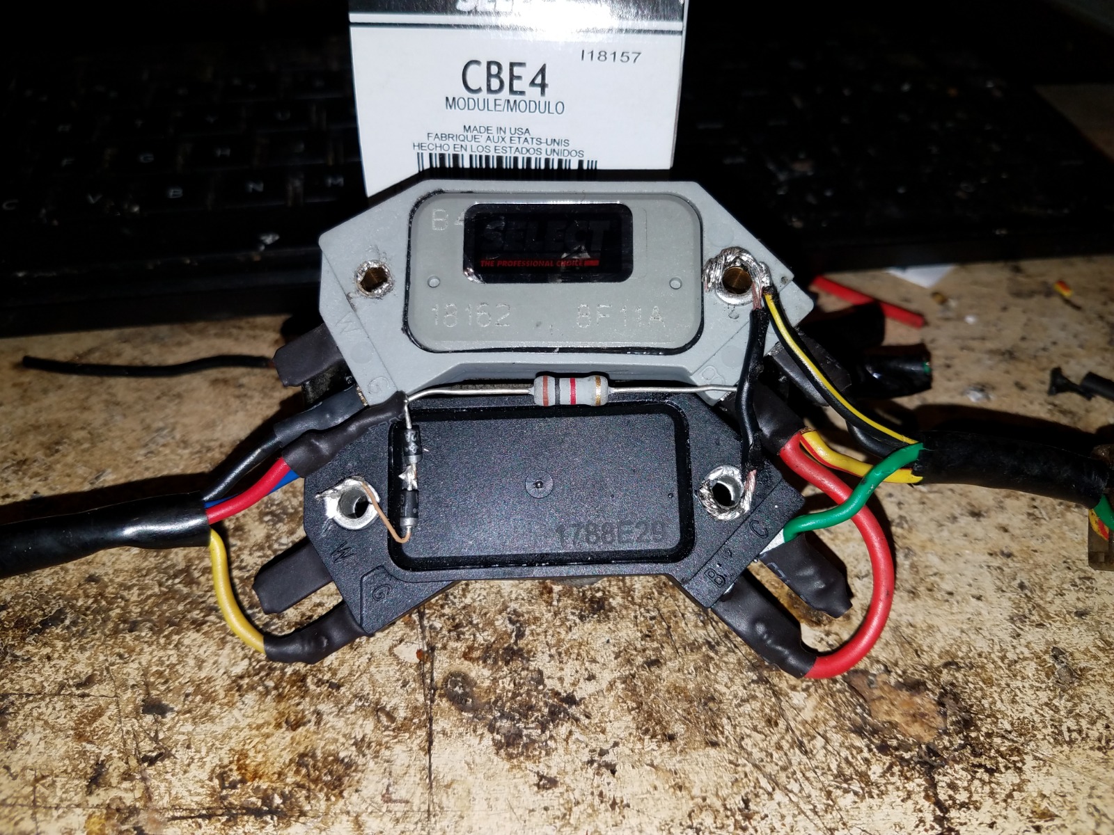
The reason I'm digging up this old thread is to ask if you've ever come to any conclusions about the newer modules. I just finished building my '80 KZ750 ltd and after running through every possible procedure to rectify a cyl 1&4 cold-fire, I realized that my igniter was bad, and ouch! The prices are absurd, but I knew there had to be a work-around. I found your info earlier today and grabbed a couple modules and had the components in stock in my shop. But Autozone only had one DR100, so I grabbed a CBE4 from Advance. I got the whole system wired up, but after stumbling upon this, I'm wondering if I made a mistake by grabbing the CBE4 in my haste to get this done tonight. I'll attach a pic showing the system wired up and the box for the BWD module. It doesn't specify CBE4P, just CBE4, so I'm wondering if I'll be able to make do with this, and if not, is there anything else I need to be aware of that's come to your attention since your last response here? I would greatly appreciate any info you're willing to give me about this. Thanks!
The following user(s) said Thank You: loudhvx
Please Log in or Create an account to join the conversation.
- loudhvx
-
- Offline
- KZr Legend
-
Registered
- Posts: 10863
- Thanks: 1622
Re: HEI Conversion question
12 Oct 2018 12:30 - 12 Oct 2018 12:47
Hi Nautilus88 and welcome to Kzrider,
Thanks for the kind words. Yes, I agree, the simplicity of the final design can hide the amount of work it took to get there. I find it's really easy to make a really complicated solution, and that solution appears to have taken a lot of work. It's exactly the opposite most of the time. Throwing a bunch of parts at a problem looks impressive, but it's often a shortcut.
Regarding the 4-pin modules:
I have pretty much abandoned working with them because there are so many different manufacturers now, and they all can easily change the module's operation with a simple firmware change without notice, and none of them have a datasheet to begin with. It's a designer's nightmare, really. It's like designing a guitar for mass-production, but your neck supplier keeps changing the tone-length randomly without any notice.
20 years ago, most/all modules were based on the Wells DR100 and were actually made in Wisconsin. Now they can be made anywhere and in many different factories. The original DR100 conformed nicely because it was based on the Motorola MC3334 chip, for which there was an actual datasheet. Most new ones are not, and most likely the chip will become unavailable, if it isn't already. The new ones most likely use the ubiquitous micro-controller which is a firmware based design.
The only reliable, simple test I could come up with is the 9v battery test. But it requires the module to be removed from circuit. (I see it looks like you soldered the modules into the wiring.)
Your CBE4 looks like there is no ground tab on the side with gray plastic. This is promising since the older CBE4/CBE4P were from the 1.25v family (DR100 family). The newer, non-conforming CBE4/CBE4P modules have a little ground tab on the side. At least the ones I bought had the tab, and they were black plastic.
Also, regarding the solder (you've obviously had experience soldering to components! ) , be aware that some modules don't use the bolt-holes as the actual ground. The real ground point is the heatsink on the back. The bolt-holes become grounded when a mounting bolt pinches the bolt-hole's metal tube against the heatsink on the back. If there is no bolt going through the bolt-hole, the heatsink may not make good contact with the bolt-hole. This results in a flakey ground which is difficult to diagnose.
Here's a link to the test page and more details about HEI modules in general in case you haven't seen it.
s3.amazonaws.com/gpzweb/Ignition/HeiModules/HeiModules.html
There are many websites that store old, outdated versions of my webpages. The only one I keep current regarding the HEI modules for Kz's is the following one (at least for now).
s3.amazonaws.com/gpzweb/Ignition/GPZgmHEImod.html
I am slowly working on ignition circuits that will replace the HEI-based ones. They will use discrete parts so will be a bit more involved parts-wise, but the parts will be non-changing with datasheets, and will likely be much cheaper than the HEI modules anyway.
So far I have only finished the coil tester. s3.amazonaws.com/gpzweb/Ignition/CoilTes...ilTesterIgbt555.html
Next will be a points-driven module, as that should be relatively simple.
Then I'll start on KZ electronic ignition modules.
1981 KZ550 D1 gpz.
Kz550 valve train warning.
Other links.
Kz550 valve train warning.
Other links.
Last edit: 12 Oct 2018 12:47 by loudhvx.
Please Log in or Create an account to join the conversation.
- Nautilus88
-
- Offline
- User
-
Registered
- Posts: 5
- Thanks: 4
Re: HEI Conversion question
12 Oct 2018 14:31
You're welcome! And thank you for all the excellent information! I couldn't agree more about simpler results taking the most work, but being the best approach. I'm currently building a guitar with a really complicated switching setup and have been obsessing about how to design the most simple, elegant, and intuitive switching configuration. Most guitars like this will have extra knobs and switches plastered all over the place. And while it looks impressive, its really not. Nor is it intuitive to use. I've spent months now re-configuring the layout to find a simple solution and I'm close to finalizing my schematic for it (with the help of some excellent new components from CTS). It doesn't have any extra knobs or switches, but has triple the configuration options, all laid out in a very intuitive manner, with different configurations automatically compensating for their own parameters. I'm very proud of the results, but good god has it been a nightmare to design. Can't tell by looking at it though!I won't pummel you with the details, but I'm sure that's something you'd take interest in. Enough about that though! Point being; I absolutely agree and understand!
Anyway! Your analogy about the necks is perfect(good thing I make my own, ha)! I absolutely understand that. I run into the same problems repairing vintage equipment. Obsolescence can be a good thing, but when sub-components start being replaced, the parts don't perform the same at all. And that's what we're running into now. I tried to find datasheets for that exact reason but that was unfortunately futile, as you stated.
I found your page about testing them, so I'll give that a shot tonight and hope for at least one of them to perform within the parameters you outlined. The CBE4 module does in fact have a ground tab on the side that isn't visible in the picture. So I'm guessing that one will be a no-go. I did check the bolt holes for continuity to the heat sink on both units and they all seem to be grounded well besides the top left(which I left out for that reason), though I was going to rely on the bolts for a sure connection. So that's an important bit of info to consider.
Also, don't mind my sloppy solder job! haha. I wasn't in the shop and was stuck using the garbage iron I have at home with a cruddy old tip on it. But yes, all of the joints are soldered. I prefer to use solder when possible, thought now I wish I would have just used connectors at first. No returning these now! I didn't realize there were issues until I started digging through the forums after I had everything soldered up.
I'll let you know how things work out. I'm anxious to get this bike on the road before it gets too cold out, so I'm hoping I can get lucky with the autozone model. Had a friend there order one and it should be in by now, so if they're both within spec, I'll be a happy camper.
I look forward to seeing your new design! I'm buying a KZ650 this weekend and would love to use your new ignition circuit on that as well. I'm nowhere near your level of expertise so I'll have to rely on you for the design process haha. Again, Lou, thank you a ton for all your hard work. You're a hero to a lot of people for what you've done. Most of us can put together a circuit, but designing it from scratch and posting it for free for the world to use?! That's not only next-level expertise, but it's very selfless and kind of you.
I'll let you know what happens tonight and post the test results. At least so you have info about these modules and whether they're usable or not.
Please Log in or Create an account to join the conversation.
- Nautilus88
-
- Offline
- User
-
Registered
- Posts: 5
- Thanks: 4
Re: HEI Conversion question
12 Oct 2018 16:01
So I just tested the units. I'm using a 10v 700mA power supply that really puts out 12 volts. The CBE4 is indeed reading 0 on W when powered as per your diagram.
I picked up the other Duralast DR100 unit and tested both of them. They both put out 1.30v on W. Strangely, none of the resistance readings are giving me anything but infinite, except the measurement between W and G, which is showing 20K ohms.
I'm going to take the voltage readings as a good sign for now though. My only question is this: Do I use your bias circuit or ground directly to W? I'm assuming I need to use your bias circuit, but I figure it can't hurt to check.
Please Log in or Create an account to join the conversation.
- loudhvx
-
- Offline
- KZr Legend
-
Registered
- Posts: 10863
- Thanks: 1622
Re: HEI Conversion question
12 Oct 2018 19:37
Solder doesn't have to look pretty, it just has to look like it "flowed". I was impressed you got a good looking solder joint without the plastic looking all burned up. Those terminals are not meant to be soldered, so it usually takes a lot of extra heat to flow (like soldering to the back of a pot on a Chinese LP knockoff ") ). I'd be interested to see your solution for the pickup configs.
). I'd be interested to see your solution for the pickup configs.
Your DR100's do look to be promising. (I think the CBE4 will have to be shelved or used for destructive testing.)
The ohm tests on non-linear devices can be all but meaningless. There are some resistors involved, so the 20k ohms sounds ok.
The W terminals will stay unconnected. The bias circuit should be wired per diagram (which I think is how you have it in the photos).
). I'd be interested to see your solution for the pickup configs.Your DR100's do look to be promising. (I think the CBE4 will have to be shelved or used for destructive testing.)
The ohm tests on non-linear devices can be all but meaningless. There are some resistors involved, so the 20k ohms sounds ok.
The W terminals will stay unconnected. The bias circuit should be wired per diagram (which I think is how you have it in the photos).
1981 KZ550 D1 gpz.
Kz550 valve train warning.
Other links.
Kz550 valve train warning.
Other links.
Please Log in or Create an account to join the conversation.
- Nautilus88
-
- Offline
- User
-
Registered
- Posts: 5
- Thanks: 4
Re: HEI Conversion question
12 Feb 2021 21:06
2+ years later, and I'm back with another question haha. I never saw your reply, but to let you know, I did end up getting this all working (and those pickups! ). I can't remember, but I may have replaced the CBE4 with a DR100. Regardless, the bike has ran well since then, besides a few other issues. Thank you again for all of your help! If I can dig up that pickup wiring diagram, I'll share it with you. It was a nightmare to sort through, but it worked out great.
I'm gearing up for riding season and will start working on my bike tomorrow. I was curious about whether or not you've gotten anywhere with those new-and-improved circuits. I'm planning on gutting my wiring and completely redoing it. I figured I'd upgrade if any new approach has come to fruition.
I look forward to hearing back from you, and I hope you're doing well.
). I can't remember, but I may have replaced the CBE4 with a DR100. Regardless, the bike has ran well since then, besides a few other issues. Thank you again for all of your help! If I can dig up that pickup wiring diagram, I'll share it with you. It was a nightmare to sort through, but it worked out great.I'm gearing up for riding season and will start working on my bike tomorrow. I was curious about whether or not you've gotten anywhere with those new-and-improved circuits. I'm planning on gutting my wiring and completely redoing it. I figured I'd upgrade if any new approach has come to fruition.
I look forward to hearing back from you, and I hope you're doing well.
The following user(s) said Thank You: loudhvx
Please Log in or Create an account to join the conversation.
- loudhvx
-
- Offline
- KZr Legend
-
Registered
- Posts: 10863
- Thanks: 1622
Re: HEI Conversion question
13 Feb 2021 15:28 - 13 Feb 2021 15:30
Hi, thanks for the update. I'm glad you got it running on the HEI modules. Good to know you can still get some that work.
I haven't gotten to design a module using IGBT's yet, but I'll eventually get to it I hope.
This one using Darlington transistors pre-dates the HEI version. It uses discrete parts and works well, but unfortunately Radio Shack is out of business and that's where I got most of the parts from. I'm sure somebody sells substitute parts online.
s3.amazonaws.com/gpzweb/Ignition/GPZignitionMod.html
The HEI modules will be about as good as anything I would design. The only advantage of using discrete parts is that you know what you are getting when you buy the parts. That's no longer true with the 4-pin HEI modules.
1981 KZ550 D1 gpz.
Kz550 valve train warning.
Other links.
Kz550 valve train warning.
Other links.
Last edit: 13 Feb 2021 15:30 by loudhvx.
Please Log in or Create an account to join the conversation.
Moderators: Street Fighter LTD