
Loudhvx's ignitor diagram
- Schorly
-
- Offline
- User
-

Registered
- Posts: 82
- Thanks: 1
Re: Loudhvx's ignitor diagram
07 Jan 2010 06:37
I have taken all spark plugs out, cleaned them and the bike finally started. I took it for a spin and all worked fine. Plugs in cylinder 3 and 4 were quite black. 1 and 2 are fine, but I know that I am burning quite a bit oil. I replaced all valve guide seals and checked the guides last summer, but I am still using a lot of oil. The funny thing is that there is no smoke from the exhaust, as if the engine needs the oil. I learnt to live with this situation.
Coming back to the voltage drop. I used some contact cleaner form an electronics store to clean the emergency stop. The fuse I have replaced with a new one. How much if at all could the voltage drop when the starter motor is running?
My next changes are the HDI modules and the relay wiring, which bypasses all the ‘voltage loosing’ connectors, switches and cables. I hope the spark will become juicer and maybe I even eliminate the sooty looking plugs in #3 and #4?!
1982 KZ1000 CSR M
Please Log in or Create an account to join the conversation.
- MFolks
-

- Offline
- User
-
Registered
- Posts: 6650
- Thanks: 541
Re: Loudhvx's ignitor diagram
07 Jan 2010 11:47
New high tension leads(what we call sparkplug wires)along with new sparkplug caps should improve the spark energy.
If the high tension leads are not molded into the ignition coils, 7mm leads from the local hot rod speed shop should fit. If the leads are molded in, NGK makes a splice for joining old and new leads: www.z1enterprises.com/detail.aspx?ID=1890
I'd suggest not running radio frequency surpression(RFI) caps (the type that came with the bike)with the non metallic leads as this can greatly reduce the spark energies.
In summation, if the replacement high tension leads are copper/metallic, use the NGK sparkplug caps for electrical noise surpression(the pop and stutter heard on radio's).
If the leads are of the carbon fiber string composition, they already will supress the RFI and do not need additional electrical noise reduction and will work with simple sparkplug caps.
1982 GPZ1100 B2
General Dynamics/Convair 1983-1993
GLCM BGM-109 Tomahawk, AGM-129A Advanced Cruise Missile (ACM)
General Dynamics/Convair 1983-1993
GLCM BGM-109 Tomahawk, AGM-129A Advanced Cruise Missile (ACM)
Please Log in or Create an account to join the conversation.
- MFolks
-
- Offline
- User
-
Registered
- Posts: 6650
- Thanks: 541
Re: Loudhvx's ignitor diagram
07 Jan 2010 13:15
To follow up: What came from the Kawasaki factory was sparkplug caps with resistors inside. After time and heat exposure, the resistor(s) can change by increasing/decreasing resistance or just fail and be open electricaly.
1982 GPZ1100 B2
General Dynamics/Convair 1983-1993
GLCM BGM-109 Tomahawk, AGM-129A Advanced Cruise Missile (ACM)
General Dynamics/Convair 1983-1993
GLCM BGM-109 Tomahawk, AGM-129A Advanced Cruise Missile (ACM)
Please Log in or Create an account to join the conversation.
- Schorly
-
- Offline
- User
-
Registered
- Posts: 82
- Thanks: 1
Re: Loudhvx's ignitor diagram
08 Jan 2010 00:29
I am not sure what I have in terms of spark plugs and leads. I know the leads are not moulded in to the coil and I should be able to replace them.
But I still don't know if it is normal for the voltage to drop down to 6V-7V when the starter motor is running. This would mean that whatever I do with improving the wiring, connectors and switches, I still only see 6V-7V on the primary side of the coil when starting the engine. And I would assume that a good spark is needed to fire a cold engine, which stood for some time?
But I still don't know if it is normal for the voltage to drop down to 6V-7V when the starter motor is running. This would mean that whatever I do with improving the wiring, connectors and switches, I still only see 6V-7V on the primary side of the coil when starting the engine. And I would assume that a good spark is needed to fire a cold engine, which stood for some time?
1982 KZ1000 CSR M
Please Log in or Create an account to join the conversation.
- ward
-

- Offline
- User
-
Registered
- Posts: 1
- Thanks: 0
Re: Loudhvx's ignitor diagram
28 Jan 2010 12:47
Loudhvx-
i was wondering if the method illustrated in your "diagram for a KZ twin version" would work for an older twin? i have a '76 kz750b1, and the starter is completely unreliable, so i'm trying to get an easier start on kick, also, the plugs foul really quickly, which i'm guessing your method would help as well.
thanks in advance for all the wonderful information you and everyone else has put up here.. what a great find this site has been.
thanks, ward
Please Log in or Create an account to join the conversation.
- loudhvx
-

- Offline
- KZr Legend
-

Registered
- Posts: 10864
- Thanks: 1618
Re: Loudhvx's ignitor diagram
28 Jan 2010 15:32 - 28 Jan 2010 15:36
ward wrote:
As far as I know you can just put on a pickup assembly and rotor from an electronic-ignition version of the 750-twin. You'll also be better off with a hotter 2.5-ohm coil.
There is a member of the twins forum selling off a bunch of these exact things as a lot. That's Shoe48. I think he is still a member here too. Check the 3rd page of this thread:
Ivar's KZ twins forum
You can also use points to trigger a hotter coil using an HEI module if your points are in decent shape.
I should also mention, you can't use the advancer from a four-cylinder model since it turns the wrong way. But the rotors are removable, so if they caould fit mechanically, you could swap a 4-cyl rotor onto a twin's point advancer and flip the iron slug. I just can't remember if they fit or not. Steell on the twins forum might remember.
Loudhvx-
i was wondering if the method illustrated in your "diagram for a KZ twin version" would work for an older twin? i have a '76 kz750b1, and the starter is completely unreliable, so i'm trying to get an easier start on kick, also, the plugs foul really quickly, which i'm guessing your method would help as well.
thanks in advance for all the wonderful information you and everyone else has put up here.. what a great find this site has been.
thanks, ward
As far as I know you can just put on a pickup assembly and rotor from an electronic-ignition version of the 750-twin. You'll also be better off with a hotter 2.5-ohm coil.
There is a member of the twins forum selling off a bunch of these exact things as a lot. That's Shoe48. I think he is still a member here too. Check the 3rd page of this thread:
Ivar's KZ twins forum
You can also use points to trigger a hotter coil using an HEI module if your points are in decent shape.
I should also mention, you can't use the advancer from a four-cylinder model since it turns the wrong way. But the rotors are removable, so if they caould fit mechanically, you could swap a 4-cyl rotor onto a twin's point advancer and flip the iron slug. I just can't remember if they fit or not. Steell on the twins forum might remember.
1981 KZ550 D1 gpz.
Kz550 valve train warning.
Other links.
Kz550 valve train warning.
Other links.
Last edit: 28 Jan 2010 15:36 by loudhvx.
Please Log in or Create an account to join the conversation.
- Schorly
-
- Offline
- User
-
Registered
- Posts: 82
- Thanks: 1
Re: Loudhvx's ignitor diagram
29 Jan 2010 02:35 - 29 Jan 2010 02:55
I now have completed the module, found some connectors, which came from your part of the world and last weekend I plugged it in to the cabling. It worked first time and I am very pleased. The only thing is now the management of the heat. I have mounted both modules back to back on a L-shaped aluminium bracket which is 6mm thick using the heat transfer paste ( I was lucky, it came with the modules). All is mounted in to a little plastic enclosures, whereby the top section of the L-shaped bracket is forming part of the outer wall of the plastic box and is all where the heat can radiate from.

This part of the section is about 25mm x 70mm long. I left the box behind the battery holder and hope it stays cool enough.
How much heat will the modules generate? Is ‘air cooling’ the 25mm x 70mm section enough?
This part of the section is about 25mm x 70mm long. I left the box behind the battery holder and hope it stays cool enough.
How much heat will the modules generate? Is ‘air cooling’ the 25mm x 70mm section enough?
1982 KZ1000 CSR M
Attachments:
Last edit: 29 Jan 2010 02:55 by Schorly.
Please Log in or Create an account to join the conversation.
- loudhvx
-
- Offline
- KZr Legend
-
Registered
- Posts: 10864
- Thanks: 1618
Re: Loudhvx's ignitor diagram
29 Jan 2010 09:24
Schorly wrote:
Nice job.
The modules don't get very hot at all. Normally they are just warm to the touch while on the heatsink. In this particular application, each module will dissipate about 2 watts. I would think the 25mm x 70mm heatsink should be able to dissipate that without getting super hot. Just make sure to check it. If you can't touch it indefinitely from being too hot, then it may need a better heatsink mounted on top of the box.
Put up a photo if you get a chance. Itd be intersting to see. I've never gotten around to making mine look nice so it's good to see a well executed version.
This part of the section is about 25mm x 70mm long. I left the box behind the battery holder and hope it stays cool enough.
How much heat will the modules generate? Is ‘air cooling’ the 25mm x 70mm section enough?
Nice job.
The modules don't get very hot at all. Normally they are just warm to the touch while on the heatsink. In this particular application, each module will dissipate about 2 watts. I would think the 25mm x 70mm heatsink should be able to dissipate that without getting super hot. Just make sure to check it. If you can't touch it indefinitely from being too hot, then it may need a better heatsink mounted on top of the box.
Put up a photo if you get a chance. Itd be intersting to see. I've never gotten around to making mine look nice so it's good to see a well executed version.
1981 KZ550 D1 gpz.
Kz550 valve train warning.
Other links.
Kz550 valve train warning.
Other links.
Please Log in or Create an account to join the conversation.
- MFolks
-
- Offline
- User
-
Registered
- Posts: 6650
- Thanks: 541
Re: Loudhvx's ignitor diagram
29 Jan 2010 13:07
Heat transfer paste or what we call thermal paste/heatsink compound should be available at any place that works on computer upgrades.
Radio Shack in the U.S. sells a good brand many people who want to over clock their systems or install a faster processor use.
The GM modules are designed to run a V-8 engine,so your use barely gets them warm.Since the modules are readily available,finding replacements(if every needed)should be no problem.
1982 GPZ1100 B2
General Dynamics/Convair 1983-1993
GLCM BGM-109 Tomahawk, AGM-129A Advanced Cruise Missile (ACM)
General Dynamics/Convair 1983-1993
GLCM BGM-109 Tomahawk, AGM-129A Advanced Cruise Missile (ACM)
Please Log in or Create an account to join the conversation.
- Schorly
-
- Offline
- User
-
Registered
- Posts: 82
- Thanks: 1
Re: Loudhvx's ignitor diagram
30 Jan 2010 06:26 - 30 Jan 2010 06:32
loudhvx wrote:
Schorly wrote:Put up a photo if you get a chance. Itd be intersting to see. I've never gotten around to making mine look nice so it's good to see a well executed version.
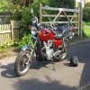
Here we go.
I just started the engine again and it is quite cold today, but it fired within the first seconds. I think it has made already a difference to the starting behaviour.
1982 KZ1000 CSR M
Attachments:
Last edit: 30 Jan 2010 06:32 by Schorly.
Please Log in or Create an account to join the conversation.
- Schorly
-
- Offline
- User
-
Registered
- Posts: 82
- Thanks: 1

- Schorly
-
- Offline
- User
-
Registered
- Posts: 82
- Thanks: 1

Moderators: Street Fighter LTD