
@#*^%$....bike died...no power...no idea.
- Old Man Rock
-
- Offline
- User
- Posts: 6224
- Thanks: 225
Re: @#*^%$....bike died...no power...no idea.
13 Oct 2008 16:23 - 13 Oct 2008 16:51
Yes, I know... I don't have the schematic for his bike.
It was more for how to troubleshoot (measure voltages and continuity) at terminations throughout the cabling for his bike. One of the reasons I asked for him to provide the schematic out of his manual then I could be more specific.
I looked all over the place for the twins... All I could come up with is the KZ750 Four Diagram.
Edited: Steell, do you have the wiring diagram for this bike. As previously mentioned, this was only a partial not full diagram for a KZ750 Four.
OMR
1976 KZ900-A4
MTC 1075cc.
Camshafts: Kawi GPZ-1100 .375 lift
Head: P&P via Larry Cavanaugh
ZX636 suspension
MIKUNI, RS-34'S...
Kerker 4-1, 1.5" comp baffle.
Dyna-S E.I.
Earls 10 row Oil Cooler
Acewell 2802 Series Speedo/Tach
Innovate LC1 Wideband 02 AFR meter
Phoenix, Az
MTC 1075cc.
Camshafts: Kawi GPZ-1100 .375 lift
Head: P&P via Larry Cavanaugh
ZX636 suspension
MIKUNI, RS-34'S...
Kerker 4-1, 1.5" comp baffle.
Dyna-S E.I.
Earls 10 row Oil Cooler
Acewell 2802 Series Speedo/Tach
Innovate LC1 Wideband 02 AFR meter
Phoenix, Az
Last edit: 13 Oct 2008 16:51 by Old Man Rock.
Please Log in or Create an account to join the conversation.
- Patton
-

- Offline
- KZr Legend
- Posts: 18640
- Thanks: 2100
Re: @#*^%$....bike died...no power...no idea.
13 Oct 2008 17:04
Here's a link to the wiring diagram from Filebase under the KZ Information tab. ")
1978 KZ750B3 wiring diagram
Or am I lost in the woods?
1978 KZ750B3 wiring diagram
Or am I lost in the woods?
1973 Z1
KZ900 LTD
KZ900 LTD
Please Log in or Create an account to join the conversation.
- Old Man Rock
-
- Offline
- User
- Posts: 6224
- Thanks: 225
Re: @#*^%$....bike died...no power...no idea.
13 Oct 2008 18:36
Ok, found the KZ750 B3 wiring diagram.. Hopefully the correct one.
members.cox.net/ruinsofstei/Z750B3%20Wiring%20Diagram.pdf
As can be reviewed in the attached file and exploded exploded view, the +12Vdc from the battery is connected to the ignition switch via the 20amp fuse. Place black probe to chassis/frame ground or battery negative terminal. You should measure +12Vdc on both sides of the 20amp fuse if good (meaning not blown open) with the meters RED probe.
On P4, second pin from the left, this feeds the +12Vdc into the ignition switch. You should measure +12Vdc on 4P and the ignition switch (Batt) terminal itself.
Turn the ignition switch to the on position, you should now measure +12Vdc on the Lg ignition switch terminal (brown conductor).
Seems this drawings is screwed up for two 4P connectors are depicted. You can still follow this no matter what it's called.
In following the brown conductor to the right handle bar switch connections you'll find this same brown conductors is terminated to the kill switch (engine stop) and headlight switch.
NOTE: Since you lost system power and lights, this is most probably a good point where your fault lies. Remove the right hand switch assembly from the handle bar and open up the assembly for inspection.
You should be able to measure +12Vdc on both switch brown conductors. If voltage present, switch on your head light switch, you should have lights but if not, measure +12Vdc on the blue /white conductor terminal.
At this point, you should also be able to measure +12Vdc on ignition switch TL1 & 2 (tail lights). With the ignition switch on, you can press the front or rear brakes as well and should operation. If not, the +12Vdc is not making it to this right hand control assembly via the ignition switch. This is why no lights nor system power.
Follow this blue/white conductor back to the 10 amp fuse and measure both sides of this fuse. This fuse feeds into a solid blue conductor which feeds into the left handle bar switch assembly dimmer switch.
Holly crap, this is getting long winded... :blink:
Anyhoot, I think you get the idea, follow the diagrams conductor color coding and you should be able to find this rather easily.
Hope this didn't bore you and let us know what you find...
OMR
1976 KZ900-A4
MTC 1075cc.
Camshafts: Kawi GPZ-1100 .375 lift
Head: P&P via Larry Cavanaugh
ZX636 suspension
MIKUNI, RS-34'S...
Kerker 4-1, 1.5" comp baffle.
Dyna-S E.I.
Earls 10 row Oil Cooler
Acewell 2802 Series Speedo/Tach
Innovate LC1 Wideband 02 AFR meter
Phoenix, Az
MTC 1075cc.
Camshafts: Kawi GPZ-1100 .375 lift
Head: P&P via Larry Cavanaugh
ZX636 suspension
MIKUNI, RS-34'S...
Kerker 4-1, 1.5" comp baffle.
Dyna-S E.I.
Earls 10 row Oil Cooler
Acewell 2802 Series Speedo/Tach
Innovate LC1 Wideband 02 AFR meter
Phoenix, Az
Attachments:
Please Log in or Create an account to join the conversation.
- dblhdr
-
- Offline
- User
- Posts: 184
- Thanks: 2
Re: @#*^%$....bike died...no power...no idea.
13 Oct 2008 19:24 - 13 Oct 2008 19:25
:huh: Ok Ok This exact thing happened to me three weeks ago. I visually checked the fuses and they all looked good. At the urging of a swell fellow on another forum I changed the fuses anyway... guess what?... the main fuse that protected everything from the fuse box to the ignition switch was indeed bad even though it looked all right. This guy on the other forum says that the solder in the fuse can melt and cause it to fail and sometimes will solidify back into a good link on occation. Mine sure didn't look blown, but a new fuse fixed me right up...
Try it you don't have anything else to lose.:blink:
Try it you don't have anything else to lose.:blink:
1981 KZ1000 Police Special coverted for civilian use with passenger seat, custom luggage rack, and paint. Daily rider.
2006 Harley Davidson Road King FLHR1
2006 Harley Davidson Road King FLHR1
Last edit: 13 Oct 2008 19:25 by dblhdr.
Please Log in or Create an account to join the conversation.
- ghunt81
-
 Topic Author
- Offline
- User
- Posts: 113
- Thanks: 0
Re: @#*^%$....bike died...no power...no idea.
13 Oct 2008 19:51
Well, I found the problem. At least it was an easy fix.
Steell, dblhdr, you guys were dead on.
This is what my fuse looked like on the main power wire-
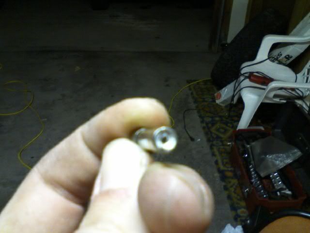
I know the pic is fuzzy, but you can see- it has a hole in the bottom of it.
I guess it had enough connectivity to work for awhile and finally let go. Weird.
I think this happened a month or so ago, I was working on the wiring and accidentally shorted something out, I did blow one of the other fuses, apparently this one almost blew but not quite.
Well, at least it's fixed, and I'm gonna go pick up some spare fuses to carry with me just in case.
Thanks everyone
Steell, dblhdr, you guys were dead on.
This is what my fuse looked like on the main power wire-
I know the pic is fuzzy, but you can see- it has a hole in the bottom of it.
I guess it had enough connectivity to work for awhile and finally let go. Weird.
I think this happened a month or so ago, I was working on the wiring and accidentally shorted something out, I did blow one of the other fuses, apparently this one almost blew but not quite.
Well, at least it's fixed, and I'm gonna go pick up some spare fuses to carry with me just in case.
Thanks everyone
1978 Kawasaki KZ750 Twin- Coil mod, Dyna coil, 7mm copper core wires
Please Log in or Create an account to join the conversation.
- MFolks
-

- Offline
- User
- Posts: 6650
- Thanks: 541
Re: @#*^%$....bike died...no power...no idea.
13 Oct 2008 20:26
These glass bodied fuses can fail with no warning as vibration can weaken the small conducting wire/metal piece or in your case creating a soft place in the end cap.
The only good way of checking this type of fuse is with a multi-meter set for continity. The fuse must be removed from the fuse holder for a good check. A self powered test light might work but could miss the potential failure if the wire is broken internally and is intermittant in use.
The only good way of checking this type of fuse is with a multi-meter set for continity. The fuse must be removed from the fuse holder for a good check. A self powered test light might work but could miss the potential failure if the wire is broken internally and is intermittant in use.
1982 GPZ1100 B2
General Dynamics/Convair 1983-1993
GLCM BGM-109 Tomahawk, AGM-129A Advanced Cruise Missile (ACM)
General Dynamics/Convair 1983-1993
GLCM BGM-109 Tomahawk, AGM-129A Advanced Cruise Missile (ACM)
Please Log in or Create an account to join the conversation.
- Old Man Rock
-
- Offline
- User
- Posts: 6224
- Thanks: 225
Re: @#*^%$....bike died...no power...no idea.
14 Oct 2008 04:39
You mean I went through all that trouble of finding a wiring diagram and explaining the voltage testing process and it was a fuse you said you checked? :blink:
hahahahahahaha... way to go, you're back on road. See, it wasn't that difficult when you put some thought into what the symptoms are (what's supposed to be and what's not) and some basic following of current flow through your cabling digram.
OHM's Law never lies!
OMR
hahahahahahaha... way to go, you're back on road. See, it wasn't that difficult when you put some thought into what the symptoms are (what's supposed to be and what's not) and some basic following of current flow through your cabling digram.
OHM's Law never lies!
OMR
1976 KZ900-A4
MTC 1075cc.
Camshafts: Kawi GPZ-1100 .375 lift
Head: P&P via Larry Cavanaugh
ZX636 suspension
MIKUNI, RS-34'S...
Kerker 4-1, 1.5" comp baffle.
Dyna-S E.I.
Earls 10 row Oil Cooler
Acewell 2802 Series Speedo/Tach
Innovate LC1 Wideband 02 AFR meter
Phoenix, Az
MTC 1075cc.
Camshafts: Kawi GPZ-1100 .375 lift
Head: P&P via Larry Cavanaugh
ZX636 suspension
MIKUNI, RS-34'S...
Kerker 4-1, 1.5" comp baffle.
Dyna-S E.I.
Earls 10 row Oil Cooler
Acewell 2802 Series Speedo/Tach
Innovate LC1 Wideband 02 AFR meter
Phoenix, Az
Please Log in or Create an account to join the conversation.