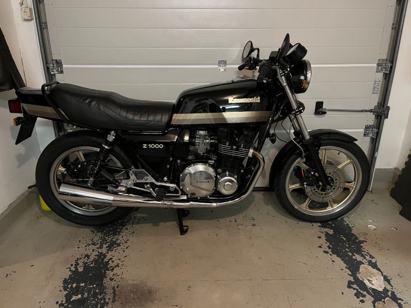
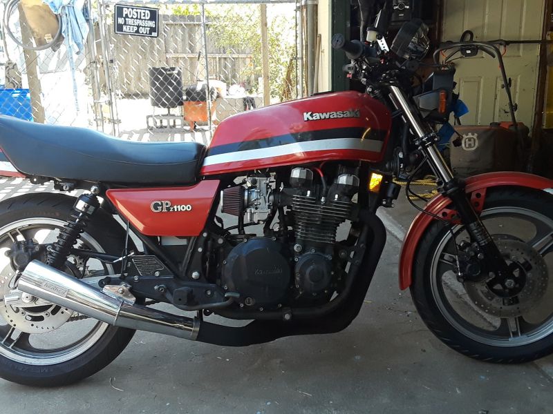
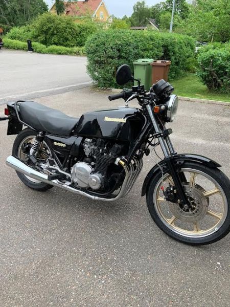
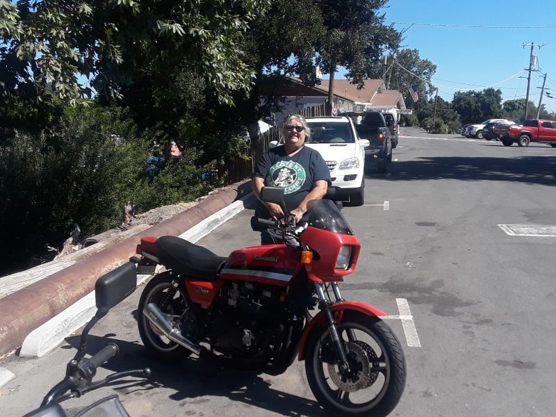
KZR's Bikes of the Month for 2024

partial loss of electric

More
22 Mar 2022 08:11 #864174 by Andyp62
partial loss of electric was created by Andyp62
My 1978 Z650 B2 has lost supply to part of the system, the main 20 amp fuse has power but the 10 amp ones don’t, the warning lights come on with the ignition, the horn and brake lights work but the starter motor and indicators don’t work, I have checked all the obvious for connections but not able to find anything, could it be the ignition switch at faulty? any help very much appreciated , the bike is a US import with six wires to the switch 
thanks

1978 Z650 B2, US import to the UK

Please Log in or Create an account to join the conversation.

More
22 Mar 2022 08:16 #864175 by Shankkole
Replied by Shankkole on topic partial loss of electric
I always start with a fresh battery when electrical issues start.
Then double check your ground.
I know its not crazy insightful, but those 2 things have been 80+percent of my electrical issues.
Be well
The following user(s) said Thank You: Andyp62

Please Log in or Create an account to join the conversation.

More
22 Mar 2022 10:11 #864179 by JR
Replied by JR on topic partial loss of electric
A fully charged battery and check ground is a good start.

Then you need a wiring diagram for your year and model - check the filebase tab and you might find one there  -  and you need a multimeter that shows 12 V DC  and resistance for connectivity.

Could be the ignition switch.
the wiring diagram will have a box diagram at bottom showing what should be connected to what when ignition switch is on and off. You can use this to check.

dont know how wires on your bike are routed but on mine the ones for the 10 amp fuses are routed through a 4 pin connector under the gas tank which also connects the wiring from the RH switch gear into the majn harness. This connector gets heat from the engine and gets brittle. Mine disintegrated years ago and caused a few electrical problems in the process.

good luck

1980 kz750E1, Delkevic exhaust
The following user(s) said Thank You: Andyp62

Please Log in or Create an account to join the conversation.

More
22 Mar 2022 11:27 #864181 by Wookie58
Replied by Wookie58 on topic partial loss of electric
Hi Andy, I would suggesting using the model recognition section in "Worksop manual" to identify what you have to start with from the Vin. You say your ign switch has six wires but in the 77 B1 manual (I could only see that and an 83 manual) both the US and European B1's (according to the wiring diagrams) only have a four wire switch ??
The following user(s) said Thank You: Andyp62

Please Log in or Create an account to join the conversation.

  • gd4now
  • Offline
  • User
  • Denco where did you go?
More
22 Mar 2022 16:04 #864193 by gd4now
Replied by gd4now on topic partial loss of electric
You indicate you have a 78 KZ650 B2 here are wiring diagrams for the North American model and the European model.

1977 KZ650 B1
Pods and Denco header


OLD KAW OWNERS SMILE ALOT

The following user(s) said Thank You: Wookie58, Andyp62

Please Log in or Create an account to join the conversation.

More
23 Mar 2022 02:38 #864208 by Wookie58
Replied by Wookie58 on topic partial loss of electric
Hi Andy, I have had a look at the wiring diagram kindly provided by gd4 and I think you have two separate issues which should be quite straight forward to sort out.
The main problem seems to centre around the right handlebar switch as this controls the starting and also provides the feed to the two 10a fuses.
Blue/ White and also Brown/White are the feeds to the fuses so are "outputs" from the switch 
Red/Yellow is the feed to the ignition coils so is also an "output" from the switch
Black is the feed to the starter via the lockout switch (I am guessing this is on the clutch lever) so is also an "output"
The Brown is the feed into the switch which powers all of the above
WHEN TESTING VOLTAGE CHECK THE BATTERY VOLTAGE FIRST -ALL READINGS SHOULD BE WITHIN 0.5v OF THE BATTERY VOLTAGE
With everything connected and the ignition switched on, test the voltage on the brown wire going into the switch (I have highlighted the connector on the diagram as I suspect this is corroded which is the cause of the problem)
If the supply voltage going into the switch is ok then check the output voltages ref the above list
Red/Yellow - test with the kill switch in the run position
Blue/White - test with the headlamp switch in the "on" position
Black - test with the kill switch set to "run" and the starter button pushed

With the indicators - these are independent of th above, check the output voltage from the ignition switch on the Orange/Green wire which feeds the flasher units for both indicators and hazard lights
Happy hunting 
The following user(s) said Thank You: Andyp62

Please Log in or Create an account to join the conversation.

More
23 Mar 2022 06:14 #864218 by Andyp62
Replied by Andyp62 on topic partial loss of electric
That’s very useful thanks I will look at that 

1978 Z650 B2, US import to the UK

Please Log in or Create an account to join the conversation.

More
23 Mar 2022 10:53 #864228 by Andyp62
Replied by Andyp62 on topic partial loss of electric
I think I must have an after market copy switch, the wire colours don’t correspond with the diagram, there is a white and other colours not on the diagram

1978 Z650 B2, US import to the UK
Attachments:

Please Log in or Create an account to join the conversation.

More
23 Mar 2022 15:13 #864241 by Wookie58
Replied by Wookie58 on topic partial loss of electric
Was it me who said this should be straightforward ( that put the kiss of death on it !!) couple of questions
  1. Does the light switch have two positions (parking light & headlight)
  2. ref the picture below, are these the wires coming from the switch ?
In the picture of the switch I can see
Red/Yellow
Blue
Blue/Red
What looks like pink (is that white)
If the wires in the picture are from the switch I can't see where the red and black are going in the switch (the red appears to be taped up as if it isn't in use ?)
The pink (or white) appears to be the feed in (brown originally) going to the kill switch along with a red/Yellow which appears to go to the starter button (are there two Red/Yellows going into the sleeving from the switch and joined together)
Does the Black go to the starter button next to the Red/Yellow
It looks like a Blue - Blue/red - white (pink) going to the lighting switch - is this correct

Once you clarify the above we should be able to work out what is going on (more pictures of the inside of the switch would be useful)


Please Log in or Create an account to join the conversation.

More
24 Mar 2022 03:59 #864259 by Andyp62
Replied by Andyp62 on topic partial loss of electric
hi there,
yes they are the wires from the switch, the colours are as you say red/ blue, blue, black, pink(looks white),  the taped up red is joined to the blue/red, there is 2 yellow/red which go to the starter button and the kill switch these are joined together, the black is to the starter button the light switch has on, off and po marked on it, the light switch wires are blue, blue/red and pink,i will add some pics
thanks

1978 Z650 B2, US import to the UK

Please Log in or Create an account to join the conversation.

More
24 Mar 2022 04:20 #864260 by Andyp62
Replied by Andyp62 on topic partial loss of electric
Some more pictures, the pink does feed the light switch and the kill switch 

1978 Z650 B2, US import to the UK

Please Log in or Create an account to join the conversation.

More
24 Mar 2022 14:13 #864273 by Wookie58
Replied by Wookie58 on topic partial loss of electric
Ok here we go -
Pink goes to Brown
Red/Yellow goes to Red/Yellow
Black goes to Black
Blue/Red goes to BrownWhite
Blue goes to Blue/White
Red not required

In this configuration when the light switch is in. The "PO" position it will feed one of the 10a fuses that powers the panel lights and front marker lights (in the front indicators)
In the "On" position it will also power the second 10a fuse that powers the headlight via the Dip/Main switch on the left handlebar switch
So back to testing:
With ignition on Pink wire should have battery voltage going into the switch
Kill switch in "Run" position Red\Yellow should have battery voltage coming out of the switch to power the coils
Kill switch in the "Run" position, push starter button Black wire should show battery voltage coming from the switch to feed the starter solenoid
Ign on, light switch in the "PO" position Blue/Red wire should show battery voltage coming from the switch to feed 10a fuse
Ign on, light switch in the "On" position Blue wire should show battery voltage coming from the switch to feed the other 10a fuse

Take all voltage readings with the black meter lead connected to battery negative terminal

Happy hunting (take 2) 
  

Please Log in or Create an account to join the conversation.

Powered by Kunena Forum

If you like KZR Please consider making a donation. Thank you.

KZRider is free, but not without cost.

Please consider chipping in a few bucks to help cover the cost of running the KZR servers.